
Sieve plate device preventing hole blocking in screening blind area
A blind area and hole blocking technology, which can be used in filter screen, solid separation, dry gas arrangement, etc., can solve the problem of the need to increase the purging pressure, and achieve the effect of strong anti-blocking effect, high purging efficiency and large purging area.
Patent Information
- Authority / Receiving Office
- CN · China
- Current Assignee / Owner
- Publication Date
- 2018-10-16
Smart Images
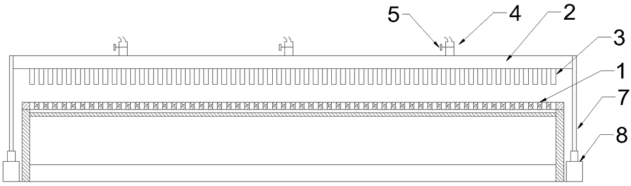
Figure 1 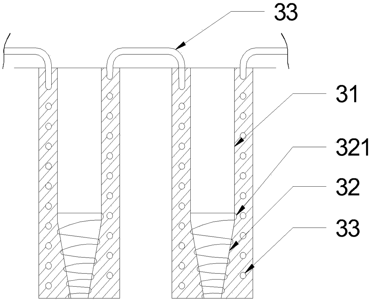
Figure 2 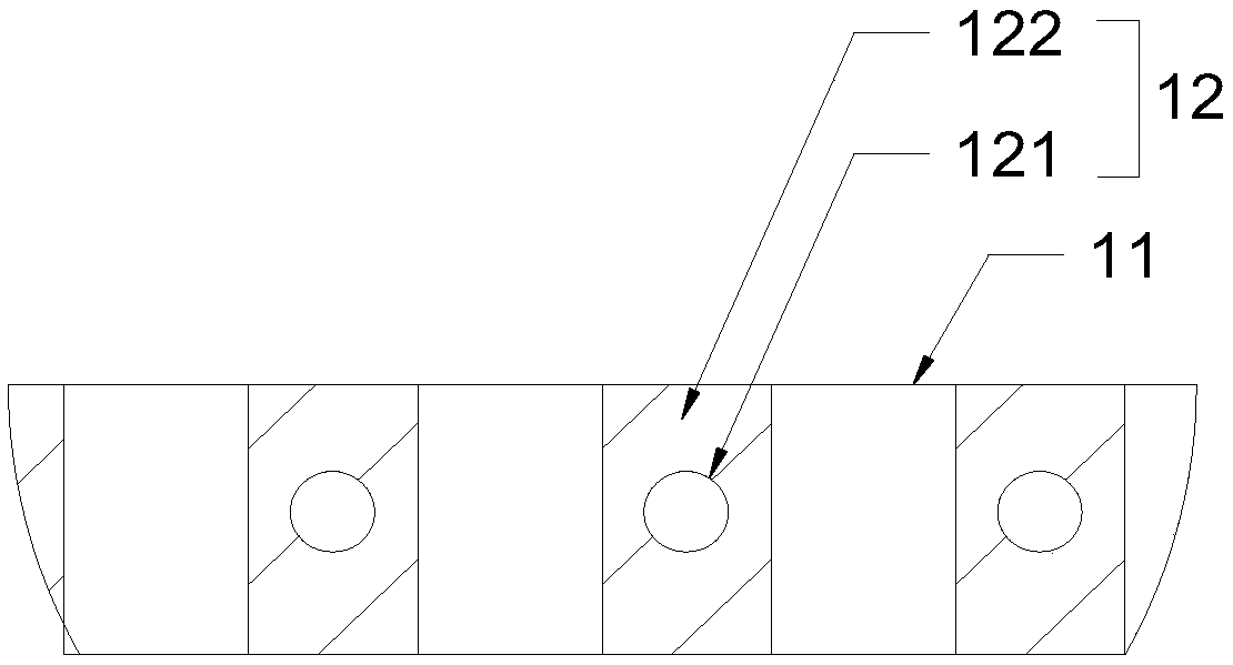
Figure 3
Abstract
Description
technical field
[0001] The invention belongs to the technical field of screening equipment, and in particular relates to a sieve plate device for preventing holes from being blocked in screening blind areas. Background technique
[0002] Fine-grained wet and sticky materials are one of the most difficult types of materials encountered in the current screening process. The sieve plates currently used in the market will encounter serious blockage in the screening blind area when processing fine-grained wet and sticky materials. This will lead to a rapid decrease in screening efficiency, and it is extremely difficult to clean the screen surface. More importantly, the working time of the entire screening system and even the crushing system will be prolonged, which will seriously increase the power consumption of the enterprise and the consumption of equipment spare parts.
[0003] The patent "An Anti-clogging Classifying Sieve" (application number: CN201410600145.5) discloses an...
Examples
Embodiment Construction
[0028] Such as figure 1 , figure 2 and Figure 5 As shown, a sieve plate device for preventing hole blocking in screening blind areas includes a pressure system and a sieve body arranged sequentially from top to bottom, and the sieve body includes a screen 1 provided with several sieve holes 11; The shape of the screen 1 matches the flat air bag 2. The bottom of the air bag 2 is provided with several needle-shaped air pipes 3 corresponding to the screen holes 11. The needle-shaped air pipe 3 includes an upper pipe end 31 communicated with the air bag 2 and The lower pipe end 32 communicating with the outside air, the pipe hole of the upper pipe end 31 is a straight cylindrical structure, and the pipe hole of the lower pipe end 32 is a cone structure with a wide top and a narrow bottom; the top of the air bag 2 is provided with a plurality of compressed air Air intake pipe 4, the compressed air intake pipe 4 is connected with the external compressed air pipeline.
[0029] S...