Intelligent blocking cleaning nozzle-containing blade rotating solid material conveying method

A solid material and blade technology, applied in the field of solid material conveying, can solve the problem of powder material blockage, reduce energy consumption and improve the efficiency of blocking prevention.

Inactive Publication Date: 2013-01-16
山东平原驰神节能设备有限公司
View PDF11 Cites 0 Cited by
  • Summary
  • Abstract
  • Description
  • Claims
  • Application Information

AI Technical Summary

Problems solved by technology

[0004] In order to solve the clogging problem when powder materials are conveyed, the designer provides a powder conveying equipment and method with functions of clearing and / or preventing clogging

Method used


Image

  • Intelligent blocking cleaning nozzle-containing blade rotating solid material conveying method

Examples


Embodiment 1

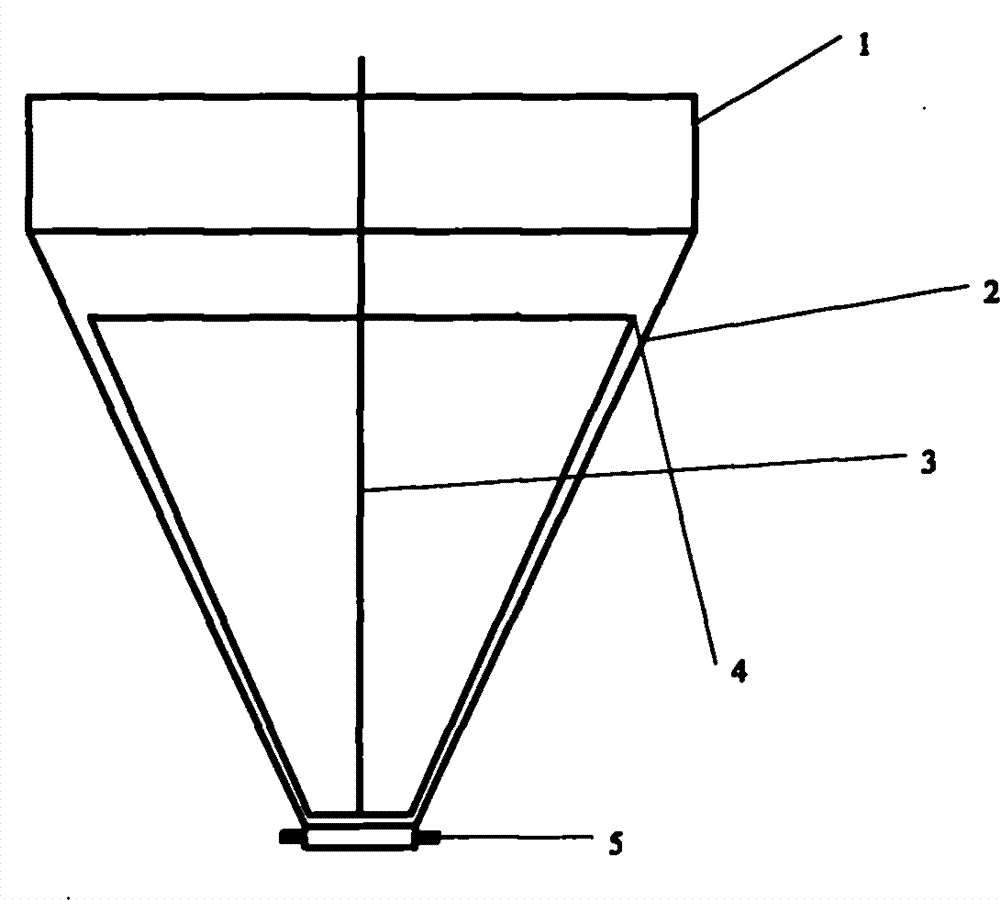
[0021] Taking pulverized coal as an example, when the flow rate drops to 70% of the normal flow rate, the rotating shaft 3 is started (the nozzle of the blade is not started), and the gap between the blade and the inner wall of the lower feeding section 2 accounts for 0.1% of the radius (inner diameter) of the lower feeding section , 0.3%, 1.0%, 1.6%, 3.3%, 6.6%, 10%, 15%. Measure the energy consumption at which flow returns to 95% of normal flow. Taking the energy consumption of 0.3% as 1, calculate the energy consumption of other proportions, see Table 1.

[0022]

0.1%

0.3%

1.0%

1.6%

3.3%

6.6%

10%

15%

energy consumption

100%

95%

85%

70%

95%

110%

[0023] Among them, 0.1% of the gaps were alarmed by the pressure sensor during the third test, and the blades were checked to be loose; 15% of them could not be restored to 95% of the normal flow.

[0024] Using 3.3% gap ...

Embodiment 2

[0026] Take pulverized coal as an example, when the flow rate drops to 70% of the normal flow rate, start the rotating shaft 3 (start the nozzle of the blade at the same time, the nozzle on the blade sprays gas downward, the angle between the nozzle and the horizontal is 75°, the blade and the lower feeding section 2 The gap on the inner wall accounts for 3.3% of the radius (inner diameter) of the lower feeding section), and the measured flow rate returns to 95% of the normal flow rate.

[0027] Taking the energy consumption of Example 1 as 1, calculate the energy consumption of Example 2, see Table 2.

[0028]

[0029] It can be seen from the table that starting the nozzle on the blade while the blade is rotating can reduce the energy consumption of anti-blocking.

Embodiment 3

[0031] Take pulverized coal as an example, when the flow rate drops to 70% of the normal flow rate, start the rotating shaft 3 (start the nozzle of the blade at the same time, the gap between the blade and the inner wall of the lower feeding section 2 accounts for 3.3% of the radius (inner diameter) of the lower feeding section) , wherein the nozzles on the blades spray gas downwards, and the included angles between the nozzles and the horizontal are 15, 35, 55, 75, 95°. Measure the energy consumption at which flow returns to 95% of normal flow. Taking the energy consumption of an included angle of 15° as 1, calculate the energy consumption of other included angles, see Table 3.

[0032]

[0033] As can be seen from the table, 75° has the lowest energy consumption.


PUM


Abstract

The invention provides a solid material conveying method which adopts solid material conveying equipment, wherein the equipment comprises at least one tapered hopper; the tapered hopper comprises an upper part feeding section and a lower part discharging section; a blade is arranged in the lower part feeding section; a clearance is formed between the blade and the internal wall of the lower part discharging section; the blade is connected with a rotating shaft and is rotated through the rotating shat, thus, the blade has a nozzle for jetting gas to an internal wall of the lower part discharging section; flow measuring equipment is arranged at an outlet section of the lower part discharging section; when flow is reduced in a certain amount by being measured via the flow measuring equipment, the rotating shaft can be started; the rotating shaft can be started only; or the rotating shaft and the nozzle of the blade can be synchronously started. With the adoption of the method provided by the invention, anti-blocking efficiency can be improved, and energy consumption can be reduced.

Description

technical field [0001] The invention belongs to the field of solid material transportation, in particular to a solid material transportation method with intelligent blockage removal and / or anti-blockage functions, in particular to a solid material with intelligent blockage removal and / or anti-blockage functions when transported along a gravity field Material delivery method. Background technique [0002] At present, solid material transportation is a very common process in the fields of chemical industry and boilers, among which the vertical transportation of solid materials is the most common process. Generally speaking, in order to save energy, the solid material transportation along the gravity field relies on gravity to carry out the free falling of solid materials for transportation. The solid material conveying equipment along the gravity field includes at least one conical hopper, and the conical hopper includes an upper feeding section and a lower feeding section. ...

Claims


Application Information

Patent Timeline
Patent Type & Authority Applications(China)
IPC IPC(8): B65D88/70B65D88/68
Inventor 程晓堂
Owner 山东平原驰神节能设备有限公司
Why Eureka
Try Eureka