A special device for replacing hot shear blades and hydraulic cylinders of a bar unit

A special device and hydraulic cylinder technology, which is applied in the field of special devices for replacing hot shear blades and hydraulic cylinders of bar units, can solve the problems of high risk, low efficiency of blades and hydraulic cylinders, etc., improve efficiency, reduce construction costs, easy-to-achieve effects

Active Publication Date: 2021-04-06
MCC5 GROUP CORP SHANGHAI
View PDF11 Cites 0 Cited by
  • Summary
  • Abstract
  • Description
  • Claims
  • Application Information

AI Technical Summary

Problems solved by technology

[0004] The technical problem to be solved by the present invention is to provide a special device for replacing the hot shear blades and hydraulic cylinders of the bar unit, which solves the problem of low efficiency and great danger in the replacement of blades and hydraulic cylinders in this field

Method used


Image

  • A special device for replacing hot shear blades and hydraulic cylinders of a bar unit
  • A special device for replacing hot shear blades and hydraulic cylinders of a bar unit
  • A special device for replacing hot shear blades and hydraulic cylinders of a bar unit

Examples


specific Embodiment 1

[0026] Specific embodiment one, such as Figure 1 to Figure 3 Shown:

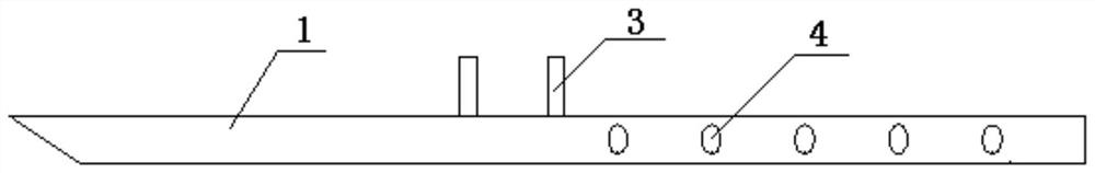
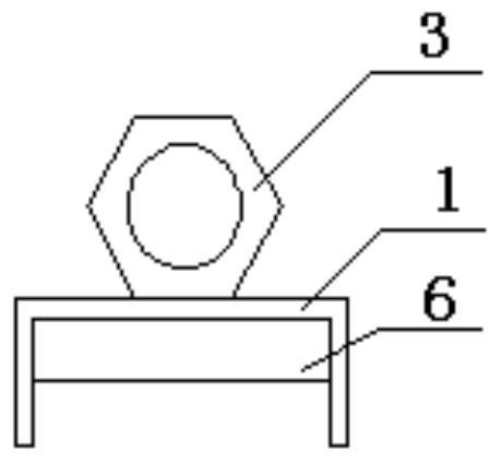
[0027] A special device for replacing hot shear blades of a bar unit, comprising a blade replacement device body 1, the blade replacement device body 1 is a channel steel structure, wherein the groove wall at one end of the channel steel has a slope, and the groove at the other end There are symmetrical positioning holes 4 on the wall; the outer side of the bottom of the groove is fixedly provided with a lifting piece.

[0028] The hoisting parts are hoisting nuts 3 .

[0029] There are 2 lifting nuts 3.

[0030] There are multiple positioning holes 4, and in this embodiment, five positioning holes are arranged on each groove wall.

[0031] A reinforcing rib 6 is arranged inside the groove, and a 10mm thick steel plate is selected for the reinforcing rib to be welded inside the groove.

[0032] This embodiment adopts 16# channel steel as the blade changing device body.

specific Embodiment 2

[0033] Specific embodiment two, such as Figure 1 to Figure 4 Shown:

[0034] A special device for hydraulic cylinder replacement, comprising a blade replacement device body and a hydraulic cylinder replacement device body 2, wherein the bottom of the blade replacement device body has a first fixing hole 5 near the end of the slope; the hydraulic cylinder replacement device body There is an arc-shaped slot at one end, and a second fixing hole 7 matching the first fixing hole 5 at the other end. The end of the arc-shaped slot has a locking structure for clamping the top of the hydraulic cylinder.

[0035] The locking structure in this embodiment is a bolt locking hole 8 .

[0036] The first fixing hole and the second fixing hole are fixed by bolts; the blade changing device body is movably connected to the fixing member, and can rotate 360 ​​degrees on a vertical plane.

[0037] The specific operation steps for replacing the blade through this device are as follows:

[0038]...


PUM


Abstract

The invention discloses a special device for hot scissor blade replacement of a bar machine, comprising a blade replacement device body, and the blade replacement device body is a channel steel structure, wherein the groove wall at one end of the channel steel is provided with an inclined surface, and the other end of the channel steel is provided with an inclined surface. The groove wall is provided with symmetrical positioning holes; the outer side of the groove bottom is fixedly provided with a hoisting piece. The device improves the efficiency of replacing blades and hydraulic cylinders in special positions, and at the same time ensures the safety of construction, effectively reduces construction costs, improves the owner's production efficiency, and achieves the purpose of increasing production and efficiency. The device in the present invention can be made of different types of waste channel steel according to the position of the blade, which is easy to implement, saves costs, and maximizes the use of waste materials.

Description

technical field [0001] The invention belongs to the field of factory equipment maintenance devices, and in particular relates to a special device for replacing hot shear blades and hydraulic cylinders of a bar unit. Background technique [0002] The hot shear blades in the big bar factory are mainly used to cut the hot steel billet, which is convenient for the billet to enter the rolling mill for rolling to prevent steel running accidents. The cutting diameter is from 150mm-300mm. With the improvement of the steel industry, the current average daily output of the big bar factory has reached 2,700 tons, the largest 6t / slab for each billet, and the smallest 3t / slab, which means that it needs to be cut 900 times a day at most, and the cutting frequency is very high. Once the blade is severely worn, the equipment clutch will burn out, so it basically needs to be cut every week Replacement once, because the blade and the blade holder are connected with the shearing mechanism with...

Claims


Application Information

Patent Timeline
Patent Type & Authority Patents(China)
IPC IPC(8): B23P19/04
CPCB23P19/04
Inventor 黄建军张兴松
Owner MCC5 GROUP CORP SHANGHAI
Why Eureka
Try Eureka