
3D printer applied to high-solid-phase ceramic slurry

A technology of 3D printer and ceramic slurry, which is applied in the field of 3D printing, can solve the problem of lower printing yield of high-solid ceramic slurry, and achieve the effect of improving the printing yield

Pending Publication Date: 2018-10-16
清紫生物科技(深圳)有限公司
View PDF17 Cites 3 Cited by
  • Summary
  • Abstract
  • Description
  • Claims
  • Application Information

AI Technical Summary

Problems solved by technology

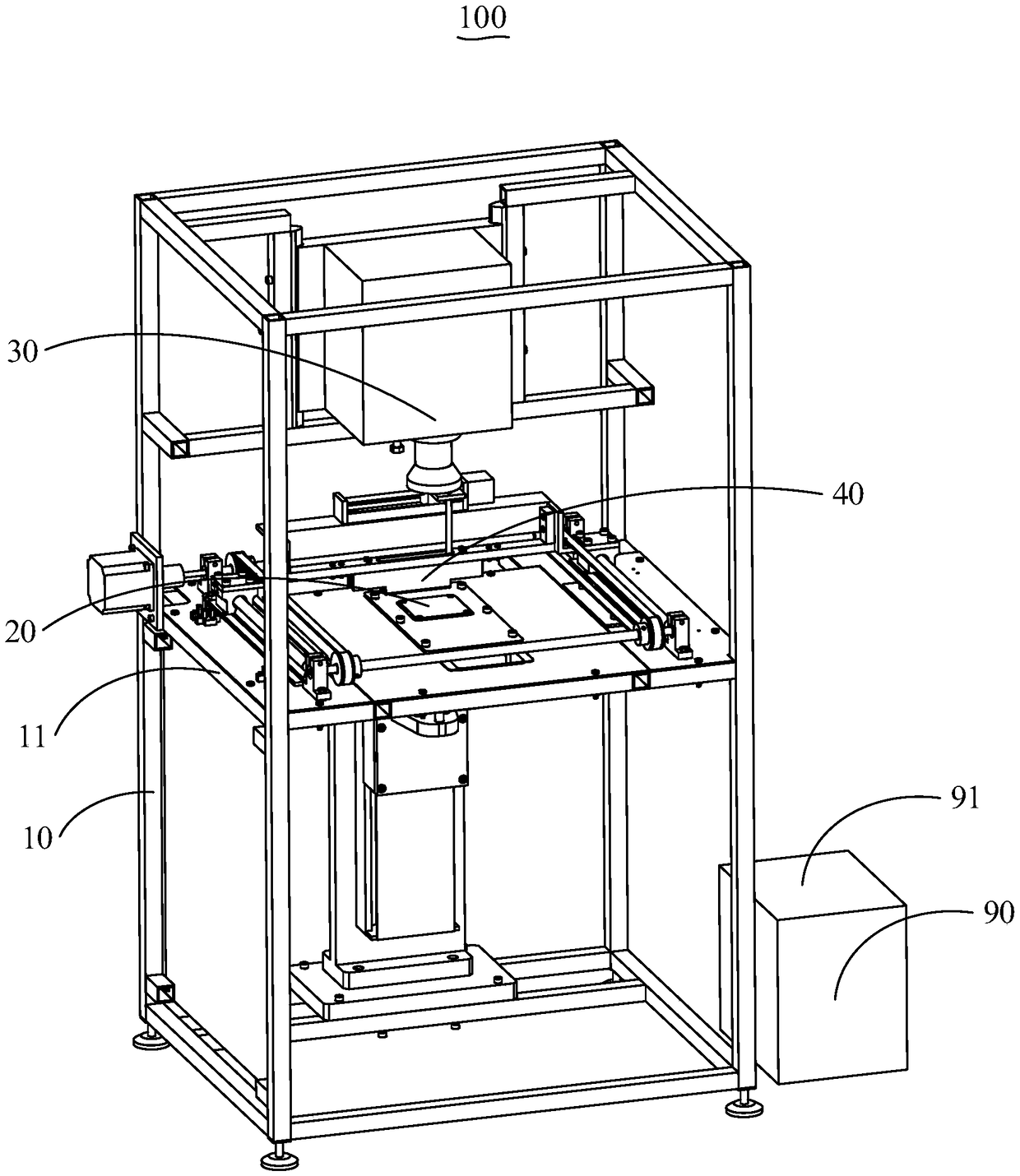
[0003] The main purpose of the present invention is to provide a 3D printer applied to high-solid phase ceramic slurry, aiming to solve the problem of lower printing yield of high-solid phase ceramic slurry in the prior art

Method used


Image

  • 3D printer applied to high-solid-phase ceramic slurry
  • 3D printer applied to high-solid-phase ceramic slurry
  • 3D printer applied to high-solid-phase ceramic slurry

Examples


Embodiment Construction

[0028] The following will clearly and completely describe the technical solutions in the embodiments of the present invention with reference to the accompanying drawings in the embodiments of the present invention. Obviously, the described embodiments are only part of the embodiments of the present invention, not all of them. Based on the embodiments of the present invention, all other embodiments obtained by persons of ordinary skill in the art without creative efforts fall within the protection scope of the present invention.

[0029] It should be noted that all directional indications (such as up, down, left, right, front, back...) in the embodiments of the present invention are only used to explain the relationship between the components in a certain posture (as shown in the accompanying drawings). Relative positional relationship, movement conditions, etc., if the specific posture changes, the directional indication will also change accordingly.

[0030] In addition, the ...


PUM


Abstract

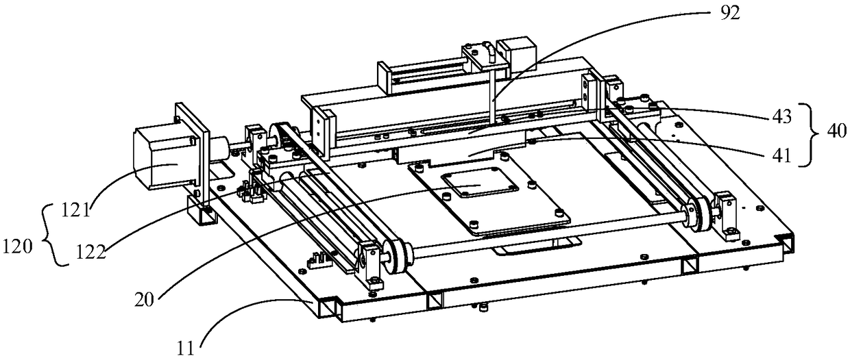
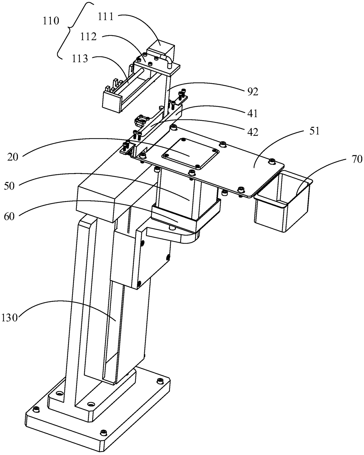
The invention provides a 3D printer applied to high-solid-phase ceramic slurry. The 3D printer applied to the high-solid-phase ceramic slurry comprises a supporting assembly, a DLP projector and a scraper assembly, wherein a printing platform capable of moving up and down is arranged in the supporting assembly; the DLP projector is arranged on the supporting assembly and located at the position above the printing platform; the scraper assembly is arranged between the printing platform and the DLP projector in a horizontal moving manner; and the scraper assembly is used for smearing the slurryon the printing platform in a scraping manner, and the DLP projector is used for downward projection and curing of the slurry on the printing platform. The 3D printer applied to the high-solid-phase ceramic slurry has the beneficial effect of increasing the printing finished product rate of the high-solid-phase ceramic slurry.

Description

technical field [0001] The invention relates to the technical field of 3D printing, in particular to a 3D printer applied to high-solid phase ceramic slurry. Background technique [0002] At present, there are three main curing methods for light-curing ceramic 3D printers: one is to solidify the ceramic mixed material in liquid form through downward projection, the second is to solidify the ceramic mixed material in slurry form through downward projection, and the third is to solidify liquid ceramic through upward projection. Mixed material. In ways 1 and 2, the printed product adheres to the carrier substrate, causing printing failure. In methods 2 and 3, due to the low solid phase content of the liquid ceramic mixture, that is, the low ceramic particles in the slurry, the printed product has a low density and a large shrinkage after degreasing and sintering. Therefore, how to improve the printing yield of high-solid-phase ceramic slurry is an urgent problem to be solved ...

Claims


Application Information

Patent Timeline
IPC IPC(8): B28B1/00B33Y10/00B33Y30/00
CPCB28B1/001B33Y10/00B33Y30/00
Inventor 陈凌枭
Owner 清紫生物科技(深圳)有限公司
Learn More