Multifunctional live working vehicle

It is a live working and multi-functional technology, which is applied in the direction of hoisting devices, lifting equipment safety devices, etc. It can solve the problems of increased risk, inability to adjust the height of the working bucket, and general practicability, so as to improve safety and practicability. Effect

Pending Publication Date: 2018-10-16
宏和机电工程有限公司
View PDF6 Cites 6 Cited by
  • Summary
  • Abstract
  • Description
  • Claims
  • Application Information

AI Technical Summary

Problems solved by technology

[0004] The purpose of the present invention is to provide a multi-functional live working vehicle to solve the problem that the staff in the above background technology can only carry the tools they need to use with them or place them on the bottom surface of the working bucket when performing electric maintenance work. , and the tool is placed on the bottom surface of the working bucket, it will cause difficulty for the staff to take it under the limitation of the working bucket space, and the practicability is general; and the existing live working vehicle has a single function and cannot adjust the height of the working bucket. Adjustment, so that there are certain limitations in the use of staff with different heights, and the safety of life is also lacking; and because the staff will work outside the work bucket, it will cause the work bucket to be unstable and increase the danger during work. sexual problems

Method used


Image

  • Multifunctional live working vehicle
  • Multifunctional live working vehicle
  • Multifunctional live working vehicle

Examples


Embodiment Construction

[0021] The following will clearly and completely describe the technical solutions in the embodiments of the present invention with reference to the accompanying drawings in the embodiments of the present invention. Obviously, the described embodiments are only some, not all, embodiments of the present invention. Based on the embodiments of the present invention, all other embodiments obtained by persons of ordinary skill in the art without making creative efforts belong to the protection scope of the present invention.

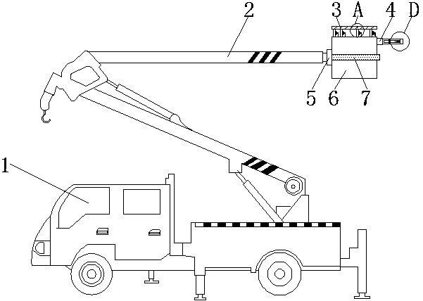
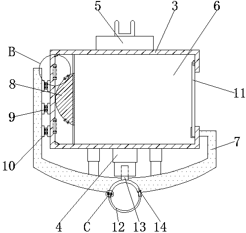
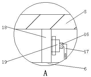
[0022] see Figure 1-7, the present invention provides a technical solution: a multifunctional live working vehicle, comprising a live working vehicle main body 1, a lifting arm 2 is movably connected to the top of the live working vehicle main body 1, and a connecting link is fixedly connected to the right end of the lifting working arm 2 The head 5 and the right side of the connecting head 5 are connected with a working bucket 6, and the surface of the worki...


PUM


Abstract

The invention relates to a multifunctional live working vehicle. The multifunctional live working vehicle comprises a live working vehicle main body. The top end of the live working vehicle main bodyis movably connected with a lifting working arm, and the right end of the lifting working arm is fixedly connected with a connecting head. Rubber blocks are connected outside buffer springs, and the left ends of the rubber blocks are adhesively connected with an anti-collision bar. The right sides of support sleeves are fixedly connected with connecting cylinders, and the insides of the connectingcylinders are movably connected with rotating rods. The right side of a second tool containing table is rotationally connected with a movable blocking rod. The top end of a rotating shaft is fixedlyconnected with a first retaining ring, and the inside of the first retaining ring is movably connected with a second retaining ring. T-shaped bolts are connected into the second retaining ring, and the right sides of the T-shaped bolts are connected with fixing nuts in a threaded manner. According to the multifunctional live working vehicle, telescopic rods can be moved inside the support sleeves,so that the height of a guard rail can be adjusted, and thus workers with different heights can be well protected, and the practicability of the device is further improved.

Description

technical field [0001] The invention relates to the technical field of live working vehicles, in particular to a multifunctional live working vehicle. Background technique [0002] Live work refers to a method of maintenance and testing on high-voltage electrical equipment without power failure; electrical equipment needs frequent testing, inspection and maintenance during long-term operation; live work is an effective measure to avoid maintenance blackouts and ensure normal power supply; The content of the operation can be divided into several aspects such as live test, live inspection and live maintenance; the objects of live work include electrical equipment in power plants and substations, overhead transmission lines, power distribution lines and power distribution equipment; the main items of live work are: : Live replacement of line pole and tower insulators, cleaning and replacement of insulators, flushing insulators with water, crimping and repairing wires and overhe...

Claims


Application Information

Patent Timeline
Patent Type & Authority Applications(China)
IPC IPC(8): B66F11/04B66F17/00
CPCB66F11/044B66F17/006
Inventor 丁绍江
Owner 宏和机电工程有限公司
Why Eureka
Try Eureka