Construction method of connection plate mounting connector of single-layer partition board
A construction method and technology of partition wall panels, which are applied in the direction of walls, building components, buildings, etc., can solve the problems of reduced sound insulation and windproof function of wall panels, sealing of gaps, etc., so as to achieve a convenient and fast installation process, improve installation efficiency, and improve safety. Effects of Sex and Reliability
- Summary
- Abstract
- Description
- Claims
- Application Information
AI Technical Summary
Problems solved by technology
Method used
Image
Examples
Embodiment 1
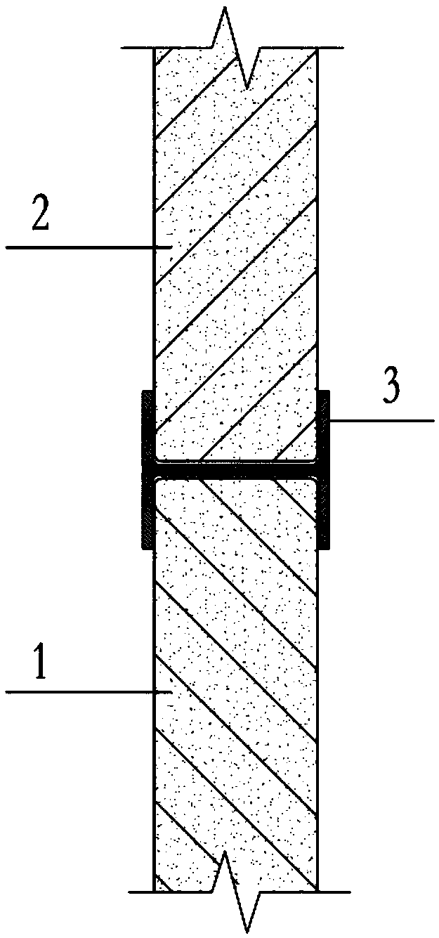
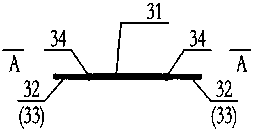
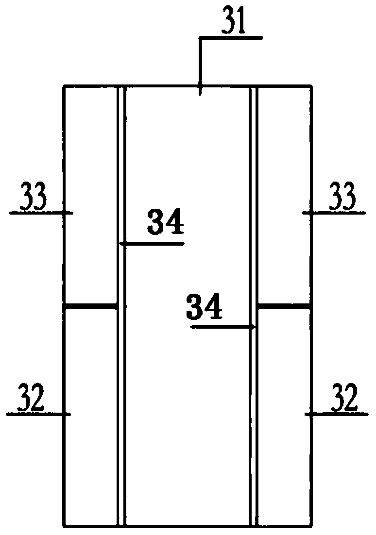
[0049] Such as Figure 1-9 As shown, a panel installation connector for a single-layer partition panel of the present invention includes a partition panel A1, a partition panel B2 and a connector 3, and the connector 3 includes a web 31, a lower flange 32 and a An upper flange plate 33, the two ends of the web 31 are respectively hinged with a lower flange plate 32 and an upper flange plate 33, and the lower flange plate 32 and the upper flange plate 33 arranged at the same end of the web 31 are hinged on the same piece On the hinge 34, the lower flange plate 32 and the upper flange plate 33 can be installed symmetrically on the two webs of the hinge 34 up and down, or they can be two webs that form a plate-like structure by face-to-face jointing, such as the lower flange plate Somewhere in 32 is a raised slat structure, and the corresponding upper flange plate 33 is a grooved slat structure matched with the raised slat structure, so that a plate-like structure can also be for...
Embodiment 2
[0065] Such as Figure 1-9 Shown is a single-layer partition board installation method for connecting parts, connecting and fixing the upper and lower two-layer partition board B2 and partition board A1 through the connector 3, including steps:
[0066] A. The partition wall panel A1 is hoisted in place, the upper end is temporarily fixed by construction measures, and the lower end is placed on the installation joint;
[0067] B. Install the connector 3 on the upper end of the partition board A1, place the web 31 of the connector 3 on the top surface of the partition board A1, and then adjust the position of the partition board A1. After the position of the partition board A1 is fixed,
[0068] Fix the lower end of the partition board A1 to install the joint, further rotate the lower flange plate 32 of the connector 3 to fit the partition board A1, and then use the fastening screw A4 to pass through the fastening hole A341 to fix the lower flange board 32, and the partition bo...
Embodiment 3
[0073] Such as Figure 1-9 Shown is a construction method for installing and connecting parts of a single-layer partition wall panel. For the fixedly installed partition wall panel B2 and partition wall panel A1, the butt joint gap between the parallel two-layer partition wall panel B2 and partition wall panel A1 is connected Part 3 is connected and fixed, including steps:
[0074] A. Insert the connector 3 into the butt joint gap between the partition board B2 and the partition board A1;
[0075] B. The lower flange plate 32 of the rotary connector 3 is attached to the partition wall plate A1, and then the fastening screw A4 is used to pass through the fastening hole A341 to fix the lower flange plate 32, and the partition wall plate A1 is installed;
[0076] C. Rotate the upper flange plate 33 to fit closely with the partition wall board B2, then use the fastening screw B5 to pass through the fastening hole B342 to fix the upper flange plate 33, and then fix the upper end o...
PUM
 Abstract
Description
Claims
Application Information
 - R&D
- Intellectual Property
- Life Sciences
- Materials
- Tech Scout
- Unparalleled Data Quality
- Higher Quality Content
- 60% Fewer Hallucinations
Browse by: Latest US Patents, China's latest patents, Technical Efficacy Thesaurus, Application Domain, Technology Topic, Popular Technical Reports.
© 2025 PatSnap. All rights reserved.Legal|Privacy policy|Modern Slavery Act Transparency Statement|Sitemap|About US| Contact US: help@patsnap.com


