Sliding door and window with baffle and baffle
A technology for sliding doors and windows and baffles, applied in the direction of door/window fittings, windows/doors, wing fan layout, etc., can solve the problems of complicated track construction space, difficult to clean, affecting the push-pull action, etc., to achieve good dust-proof effect, The effect of continuous and effective action, easy to operate
- Summary
- Abstract
- Description
- Claims
- Application Information
AI Technical Summary
Problems solved by technology
Method used
Image

Examples
Embodiment 1
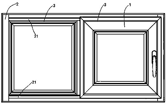
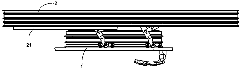
[0032] The sliding door and window with a baffle in this embodiment includes a window frame 2 and a sash 1, the sash 2 is provided with a slideway 24 and a baffle 21 for covering the slideway 24, and the sash 1 is A connecting rod opening and closing mechanism is installed, and the connecting rod opening and closing mechanism is slidably connected with a sliding assembly 14, and the sliding assembly 14 can slide in the slideway 24 to make the window sash 1 open or close, which is characterized in that :
[0033] The baffle plate 21 is movably installed on the window frame;
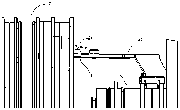
[0034] The window sash 1 or the link opening and closing mechanism is equipped with a link driving mechanism 11 for driving the baffle plate 21 to link with the window sash 1. The link driving mechanism 11 includes a connecting rod 111, a driving rod 112 and a horizontally arranged fixed rod. 113, one end of the connecting rod 111 is installed on the window sash 1 or hinged on the connecting rod opening a...
Embodiment 2
[0040] The main difference between this embodiment and the above-mentioned Embodiment 1 is that this embodiment has a sliding door and window with a baffle plate, and the linkage driving mechanism 11 also includes a bracket 15, and the bracket 15 includes a rod body connected to a fixed rod 113. The upper connecting plate 151, the lower hinged plate 152 hinged with the driving rod 112 and the support plate 153 for supporting the connecting rod 111. Connecting rod 111 is a stressed long rod, which is easy to bend under frequent stress. Because the driving rod 112 rotates frequently and is under stress, the hinge is prone to fatigue failure. This design can only replace the bracket 15, which is more convenient than replacing the fixed rod 113.
[0041] The decorative strip 3 in this embodiment is embedded in the window sash 1 and the window frame 2, for details, please refer to the attached Figure 11 and 12 , directly reserve mosaic grooves on the profiles of the window frame...
Embodiment 3
[0043] The difference between this embodiment and Embodiment 1 is that the bracket 15 of this embodiment includes a connecting sleeve 154 and a U-shaped groove plate 155 connected to the connecting sleeve 154 via a riser and arranged horizontally, and the fixing rod 113 is a slender piece , the strength and stiffness of the screw holes will inevitably decrease, and the diameter of the fixing rod 113 is even smaller in smaller windows, and it is even difficult to realize screw connection. Therefore, this design form of this embodiment maintains the strength of the fixing rod 113 more. The connecting sleeve 154 is sleeved on the fixed rod 113, such as Figure 13 and 14 As shown, the sleeve hole of the connecting sleeve 154 is a circular flat bottom opening, which acts as an axial limit to prevent it from rotating on the fixed rod. The driving rod 112 is hinged with the U-shaped groove plate 155 after being inserted into the U-shaped groove plate 155 .
PUM
 Abstract
Description
Claims
Application Information
 - R&D
- Intellectual Property
- Life Sciences
- Materials
- Tech Scout
- Unparalleled Data Quality
- Higher Quality Content
- 60% Fewer Hallucinations
Browse by: Latest US Patents, China's latest patents, Technical Efficacy Thesaurus, Application Domain, Technology Topic, Popular Technical Reports.
© 2025 PatSnap. All rights reserved.Legal|Privacy policy|Modern Slavery Act Transparency Statement|Sitemap|About US| Contact US: help@patsnap.com