Electronic expansion valve

An electronic expansion valve and valve seat technology, which is applied in the field of expansion valves, can solve the problems affecting the use effect of electronic expansion valves, the difficulty of valve needle processing, and high assembly precision requirements, so as to ensure the use effect and service life and improve work stability. , Reduce the effect of processing difficulty

Active Publication Date: 2018-10-16
DUNAN ENVIRONMENT TECH
View PDF7 Cites 2 Cited by
  • Summary
  • Abstract
  • Description
  • Claims
  • Application Information

AI Technical Summary

Problems solved by technology

[0004] However, in order to achieve the purpose of reducing the pressure difference resistance of the valve needle, the above-mentioned existing electronic expansion valve needs to set up a balance chamber 107 and a bypass channel 109 on the seat body, which is difficult to process, difficult to manufacture, and requires high assembly accuracy. The overall balance structure more complex
In addition, because the valve needle 31 needs to go down deep into the balance chamber 107, the valve needle is slender, the processing of the valve needle is difficult, and the slender valve needle is easily deformed after being stressed, which affects the overall use effect of the electronic expansion valve.

Method used


Image

  • Electronic expansion valve
  • Electronic expansion valve
  • Electronic expansion valve

Examples


Embodiment 1

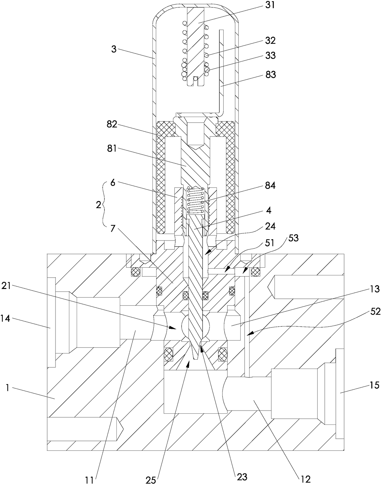
[0035] Such as figure 2 As shown, the electronic expansion valve provided by Embodiment 1 of the present invention includes a valve body 1 , a valve seat 2 and a sleeve 3 , the valve seat is fixed on the valve body, and the sleeve is fixedly sleeved on the valve seat.

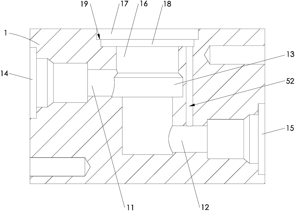
[0036] Such as image 3 As shown, the valve body 1 is provided with a first passage 11, a second passage 12 and an intermediate passage 13 between the first and second passages, and one side of the valve body is provided with a first port 14 communicating with the first passage 11 , The other side is provided with a second port 15 communicating with the second channel 12 . The top of the middle channel 13 is provided with a mounting hole 16 for the valve seat 1 to be loaded into. The top of the mounting hole is provided with a counterbore 17 coincident with the axis of the mounting hole. The aperture of the counterbore is larger than the aperture of the mounting hole.

[0037] Such as Figure 4 As shown, th...

Embodiment 2

[0052] Such as Figure 5 As shown, the difference between the second embodiment and the first embodiment above is that the valve seat 2 includes a nut seat 9 and a valve port seat 7 fixed together after separate molding, and the nut seat 9 is provided with a nut 6 and a fixing part 26 , the connecting portion 27 and the upper balance hole 51 are all located on the nut seat 9, and the valve port 23 is located on the valve port seat 7.

[0053] When the valve seat adopts a split structure, each part has a simple structure and is easy to process, and each part can be assembled with different materials after processing, which is conducive to reducing material costs while meeting the use requirements.

Embodiment 3

[0055] Such as Figure 6 As shown, the difference between the third embodiment and the first embodiment above is that the valve seat 2 includes a nut 6 and a valve port seat 7 fixed together after separate molding, the valve port 23, the upper balance hole 51, the fixing part 26 and the The connecting parts 27 are all arranged on the valve seat 7 . The top of the valve seat 7 is provided with a fixing hole matching the bottom of the nut 6, and the nut is fixed on the valve seat by means of welding or interference fit.

[0056] When the valve seat adopts a split structure, each part has a simple structure and is easy to process, and each part can be assembled with different materials after processing, which is conducive to reducing material costs while meeting the use requirements.


PUM


Abstract

The invention discloses an electronic expansion valve, and belongs to the technical field of expansion valves. The electronic expansion valve comprises a valve seat and a sleeve, wherein the valve seat is arranged on a valve body, and the sleeve is fixed on the valve seat; a first channel and a second channel are formed in the valve body, and the valve seat is provided with a circulation channel located between the first channel and the second channel and a valve port; a valve needle and a rotor assembly used for driving the valve needle to move back and forth are arranged in the sleeve, a guide hole matched with the valve needle is formed in the valve seat, and the valve needle is opened or closed when the valve needle moves back and forth along the guide hole; and an upper valve cavity communicating with the interior of the sleeve is arranged on one side of the valve seat, a lower valve cavity communicating with the second channel is arranged on other side of the valve seat, and a balance hole for communicating the upper valve cavity with the lower valve cavity is formed between the upper valve cavity and the lower valve cavity. According to the electronic expansion valve, the balance hole for communicating the upper valve cavity with the lower valve cavity is formed; and under the action of the balance hole, the pressure in the upper valve cavity and the pressure in the lower valve cavity are consistent, and the pressure difference formed by the upper valve cavity and the first channel on the valve needle and the pressure difference formed by the first channel and the lower valve cavity on the valve needle are counteracted by each other.

Description

technical field [0001] The invention relates to the technical field of expansion valves, in particular to an electronic expansion valve. Background technique [0002] As a flow regulating element, the electronic expansion valve adapts to the development requirements of refrigeration electromechanical integration and provides conditions for the intelligence of the refrigeration system. It is a promising self-control regulating element. The electronic expansion valve uses the principle of a stepping motor to drive the magnetic rotor part to rotate forward and reverse through the coil, and converts the rotation of the magnetic rotor part into the up and down movement of the push rod, and the push rod drives the valve needle connected to it to rise or fall Control the flow of refrigerant. [0003] The publication number is CN 106151554 A, and the publication date is that the Chinese invention patent application on November 23, 2016 discloses a kind of figure 1 In the electroni...

Claims


Application Information

Patent Timeline
Patent Type & Authority Applications(China)
IPC IPC(8): F16K1/42F16K27/02F16K1/00F16F15/067F25B41/06F25B41/35
CPCF16F15/067F16K1/00F16K1/42F16K27/0254F25B2500/13F25B41/34F25B41/31Y02B30/70
Inventor 秦艳王鑫楠王文君
Owner DUNAN ENVIRONMENT TECH
Why Eureka
Try Eureka