Pneumatic rotary executing mechanism

A pneumatic actuator and actuator technology, applied in the field of machinery, can solve problems such as safety accidents and production impacts, and achieve the effects of high precision, simple installation and convenient use.

Pending Publication Date: 2018-10-16
苏州巴恩斯通环保科技有限公司
View PDF0 Cites 0 Cited by
  • Summary
  • Abstract
  • Description
  • Claims
  • Application Information

AI Technical Summary

Problems solved by technology

[0003] In order to solve the problem that most of the existing optional control mechanisms are controlled by motors, and the electrical devices of the motors are

Method used


Image

  • Pneumatic rotary executing mechanism
  • Pneumatic rotary executing mechanism
  • Pneumatic rotary executing mechanism

Examples


Embodiment 1

[0028] Example 1: A pneumatic rotary actuator

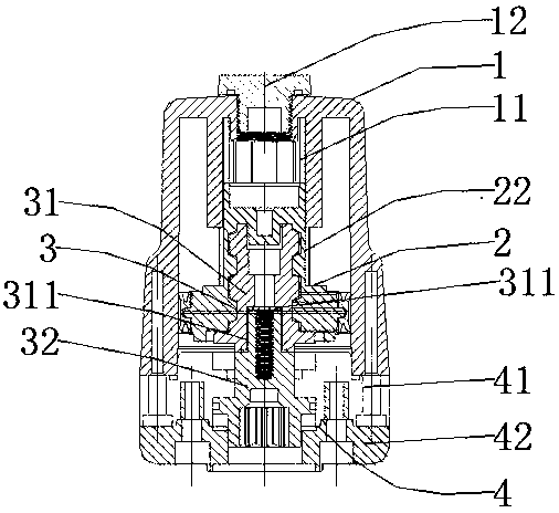
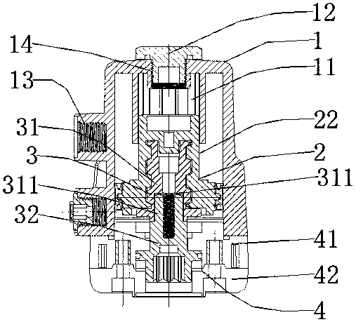
[0029] see Figures 1 to 6 , a pneumatic rotary actuator, which includes: an upper housing 1, a pneumatic actuator 2, a screw actuator 3, and a lower housing 4;

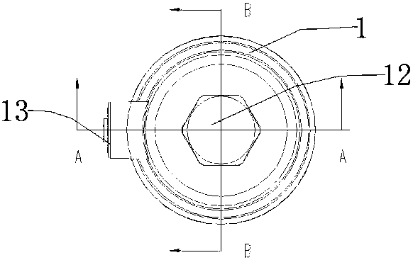
[0030] The upper casing 1 has a barrel-shaped structure, and the upper bottom is provided with a through hole 14;

[0031] The inside of the upper housing 1 is provided with a guide sleeve 11, and the inside of the guide sleeve 11 is provided with internal splines;

[0032] The guide sleeve 11 is arranged coaxially with the through hole 14;

[0033] The through hole 14 is provided with a bolt plug 12;

[0034] One side of the upper casing 1 is provided with a pneumatic control interface 13;

[0035] The pneumatic actuator 2 is piston-shaped and matches the inside of the upper casing 1;

[0036] The outer side of the pneumatic actuator 2 is provided with an external spline 22, and the external spline 22 is matched with the internal spline inside the guide sleeve 11;...


PUM


Abstract

The invention discloses a pneumatic rotary executing mechanism. The pneumatic rotary executing mechanism comprises an upper shell body, a pneumatic executing mechanism body, spiral executing mechanismbodies and a lower shell body, an inner spiral groove is formed in the inner side of the pneumatic executing mechanism body, the first spiral executing mechanism body is arranged at the lower part ofthe pneumatic executing mechanism body, and an outer spiral is arranged outside the first spiral executing mechanism body; the second spiral executing mechanism body is installed at the lower part ofthe first spiral executing mechanism body; and the lower shell body is arranged at the lower part of the upper shell body and is in bolt connection with the upper shell body. The pneumatic rotary executing mechanism can be used as a driving mechanism of a valve and other devices, such as a ball valve, and an output connecting part is connected with a valve rod of the ball valve during use; and the pneumatic rotary executing mechanism is connected with a control air source, a piston of the pneumatic executing mechanism body is pneumatically controlled to move up and down so as to achieve control of opening and closing of the ball valve. All parts of the pneumatic rotary executing mechanism are machined by adopting an injection molding technology, the parts are integrally formed, the stability is good, and the size precision is high; and the parts are made of plastic materials, so that a certain corrosion resistance effect is achieved, and the parts are suitable for being used under severe conditions.

Description

technical field [0001] The invention relates to the mechanical field, in particular to a pneumatic rotary actuator. Background technique [0002] In the field of automation control, it is often required to control the rotation of the workpiece or mechanism to perform rotary motion. The commonly used control method is to use motor control or steering gear control. Motor control requires the use of linkage mechanisms or servo control for electrodes. Steering gear and motor control are often used. When used in the field of automation, a more complex control system is required, and the control system may fail in some extreme environments. For example, the valve control mechanism or other mechanisms that use the rotation angle as the control unit are usually driven by motors, and the motor drives need to use intelligent control modules. These electrical devices are prone to safety accidents in harsh environments, and leakage and power failure will affect production. Therefore, t...

Claims


Application Information

Patent Timeline
IPC IPC(8): F16K31/12
CPCF16K31/12
Inventor 卫洋
Owner 苏州巴恩斯通环保科技有限公司
Why Eureka
Try Eureka