
Base plate of electronic device and inductor and transformer with same

A technology of electronic devices and transformers, which is applied in the field of bottom plate structure of electronic devices, can solve problems such as low installation efficiency and unfavorable automatic installation, and achieve the effect of improving efficiency, increasing size, and reducing precision requirements

Pending Publication Date: 2018-10-16
SHENZHEN FUTAI ELECTRONICS MATERIAL TECH CO LTD
View PDF0 Cites 0 Cited by
  • Summary
  • Abstract
  • Description
  • Claims
  • Application Information

AI Technical Summary

Problems solved by technology

[0005] The application provides a bottom plate of an electronic device and an inductor and a transformer with the bottom plate, which solves the problems of low installation efficiency when the existing bottom plate is installed on electronic devices such as inductors or transformers, and is not conducive to automatic installation

Method used


Image

  • Base plate of electronic device and inductor and transformer with same
  • Base plate of electronic device and inductor and transformer with same
  • Base plate of electronic device and inductor and transformer with same

Examples


Embodiment 1

[0035] The first embodiment provides an inductor, specifically an inductor with a bottom plate.

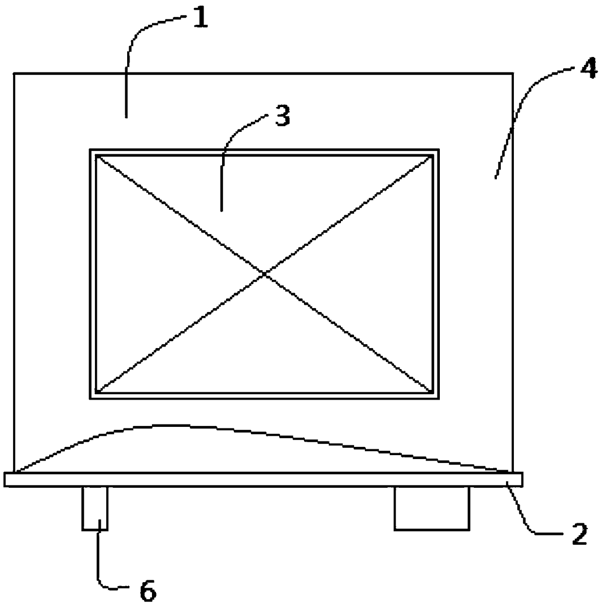
[0036] Please refer to figure 1 , the inductor 1 includes a magnetic core 3, the magnetic core 3 includes a plurality of mutually assembled magnetic pieces, the magnetic core 3 is wound with a number of copper wires to form a coil 4, and the end of the coil 4 is formed with a pair of pins 6 .

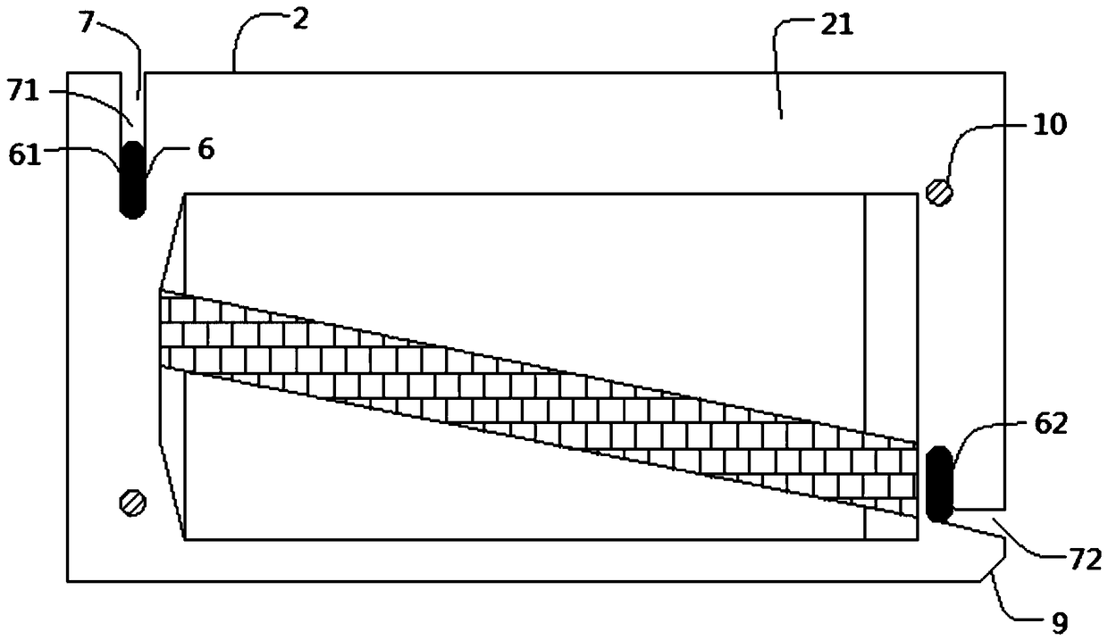
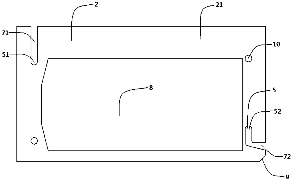
[0037] Please refer to figure 2 and image 3 , the inductor 1 also includes a bottom plate 2 . The bottom plate 2 includes a plate body 21 . In this embodiment, the shape of the plate body 21 is a rectangle. In other embodiments, other shapes such as a circle can also be used. The board body 21 is provided with a pin hole 5, the pin 6 of the coil 4 passes through the pin hole 5, the coil 4 and the board body 21 are bonded by glue, and the pin hole 5 is located at the two sides of the diagonal line of the board body 21. Each end is provided with a first pin hole 51 and a second pin ho...

Embodiment 2

[0050] The second embodiment provides a transformer, specifically a transformer with a bottom plate.

[0051] Please refer to Figure 7 , the transformer 11 includes a magnetic core 3, a coil 4 is wound on the magnetic core 3, and the coil 4 includes a primary coil and several secondary coils.

[0052] Please refer to Figure 8 , the inductor 1 further includes a bottom plate 2 , and the bottom plate 2 includes a plate body 21 . In this embodiment, the shape of the plate body 21 is a rectangle. In other embodiments, other shapes such as a circle can also be used. The board body 21 is provided with a pair of pin holes 5 , the pins 6 of the coil 4 pass through the pin holes 5 , and the coil 4 and the board body 21 are bonded by glue.

[0053] In each pair of pin holes 5, the two pin holes 5 extend in the direction of approaching or moving away from each other, and the extension direction of the pin holes 5 is defined as its length direction, that is, the direction in which th...


PUM


Abstract

The invention discloses a base plate of an electronic device and an inductor and a transformer with the same. A plurality of pin holes for inserting pins of the electronic device and a guide slot penetrating a plate body are formed in the plate body of the base plate. An opening at one end of the guide slot is communicated with a pin hole, and an opening at the other end is arranged in the side ofthe plate body. In the base plate installation process, when a pin of the electronic device (including but not limited to the inductor and the transformer) needs to be embedded in the corresponding pin hole, a user can abut the pin against the guide slot of the base plate, then push the pin to enable the pin to slide along the guide slot to be embedded in the pin hole to achieve insertion connection of the pin and the pin hole. The pin-hole alignment mode is changed to be the pin pushing-into-hole mode, and the pin can be embedded into the pin hole conveniently. On one hand, the working efficiency for assembly of the base plate on the electronic device is improved; on the other hand, the automatic assembly of the base plate on the electronic device becomes feasible.

Description

technical field [0001] The present application relates to the technical field of electronic devices, and in particular, to a bottom plate structure of an electronic device. Background technique [0002] Electronic devices are an important part of the field of electronic technology. For example, inductors and transformers are commonly used electronic components in the field of electronic technology. The uses of inductors in circuits usually include: filtering, buffering and current limiting, etc. The uses of transformers usually include: realizing Electrical isolation between adjacent systems, voltage or impedance transformation, generation of phase shift, energy storage and transmission, and voltage and current detection, etc. [0003] The bottom of the inductor and the transformer is usually installed with a bottom plate, and the way to install the bottom plate is manual installation. When installing the bottom plate, the staff first align the pins at the bottom of the indu...

Claims


Application Information

Patent Timeline
Patent Type & Authority Applications(China)
IPC IPC(8): H01F27/06
CPCH01F27/06
Inventor 朱勇陈记铭
Owner SHENZHEN FUTAI ELECTRONICS MATERIAL TECH CO LTD
Learn More