
Temperature safety warning and protection method for power transmission line of power system during oscillation period

A technology of transmission lines and power systems, applied in the direction of emergency protection circuit devices, electrical components, etc., to achieve the effects of avoiding thermal aging, protection against malfunction, and reducing hardware and labor costs

Active Publication Date: 2018-10-16
CHONGQING UNIV +1
View PDF4 Cites 3 Cited by
  • Summary
  • Abstract
  • Description
  • Claims
  • Application Information

AI Technical Summary

Problems solved by technology

[0006] Aiming at the deficiencies of the above-mentioned prior art, the present invention provides a transmission line temperature safety alarm and protection method during power system oscillation, which solves the problem that the protection is blocked by the oscillation blocking module and ignores the consideration of transmission line safety when non-fault oscillation occurs in the prior art. It can realize safety early warning and ensure reliable blocking before the temperature rise exceeds the limit, and open the blocked protection in time when the line temperature rise exceeds the limit safely, and send a trip signal to prevent the wire from being damaged due to overheating and ensure power transmission safe operation of the line

Method used


Image

  • Temperature safety warning and protection method for power transmission line of power system during oscillation period
  • Temperature safety warning and protection method for power transmission line of power system during oscillation period
  • Temperature safety warning and protection method for power transmission line of power system during oscillation period

Examples


Embodiment Construction

[0052] The present invention will be further described in detail below in conjunction with the accompanying drawings and preferred embodiments.

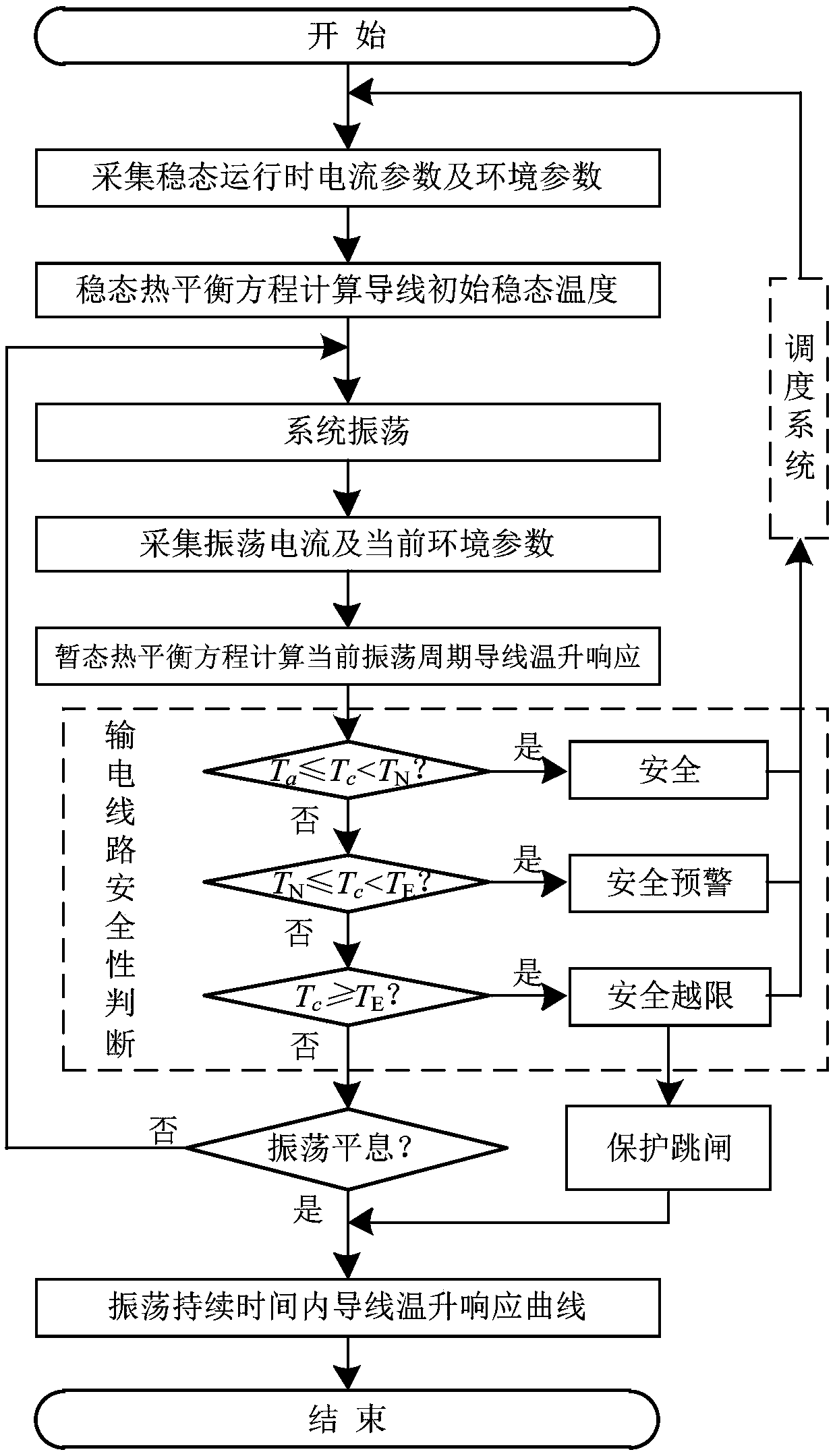
[0053] Such as figure 1 As shown, a method for safety warning of transmission line temperature during power system oscillation includes the following steps:

[0054] Step 1): Calculate the initial steady-state temperature of the transmission line during steady-state operation: collect the current and meteorological environment parameters of the transmission line during steady-state operation, according to the wire parameters of the transmission line, the real-time meteorological parameters of the area covered by the transmission line corridor and the transmission The real-time current of the line during steady-state operation, using the steady-state heat balance equation to calculate the initial steady-state temperature of the transmission line during steady-state operation; , wind speed, wind direction, sunshine, temperature and ot...


PUM


Abstract

The invention discloses a temperature safety warning and protection method for a power transmission line of power system during an oscillation period. The temperature safety warning and protection method comprises the following steps of 1) calculating an initial steady-state temperature of the power transmission line; 2) acquiring an oscillation current parameter of the power transmission line inreal time; 3) calculating temperature rising response of the power transmission line in a current oscillation period; 4) judging a current safety level according to the temperature rising response ofthe power transmission line, and sending the safety level to a dispatching system; and 5) judging whether oscillation is subsided or not, if not, returning to the step 2), if yes, obtaining a temperature rising response curve of the power transmission line in the whole oscillation period. The invention also provides a protection method for the power transmission line of the power system during theoscillation period. During the safety warning process, protection measure is started when the safety level of the power transmission line is threshold-crossing level. By the temperature safety warning and protection method, the problem that the safety of the power transmission line is neglected after oscillation shunting in the prior art is solved, safety warning can be achieved, reliable shunting of the protection before threshold crossing is ensured, and the protection timely acts and trips during safety threshold crossing.

Description

technical field [0001] The invention relates to a real-time operation safety state evaluation and protection method of a transmission line, specifically refers to a transmission line temperature safety alarm and protection method during power system oscillation, and belongs to the technical field of power system relay protection. Background technique [0002] Oscillations are the loss of synchronization of systems or power plants operating in parallel, disrupting stable operation. In the actual power system, oscillation occurs many times in the power operation of various countries. As a serious system accident, when oscillation occurs, it will seriously affect the stability of the system and the safety of the operating unit, and restrict the power transmission capacity of the power grid. The further expansion of oscillation accidents can easily cause chain trips of the whole system, causing large-scale power outages, and causing great losses to people's lives and the nation...

Claims


Application Information

Patent Timeline
Patent Type & Authority Applications(China)
IPC IPC(8): H02H7/26
CPCH02H7/262
Inventor 王建熊小伏陈璟胡剑崔勇
Owner CHONGQING UNIV
Learn More