Electrical control equipment and clamping buckle device thereof

A technology for electrical control equipment and buckle devices, which is applied in the field of electrical control equipment and buckle devices, and can solve the problems of limiting the use of C-shaped guide rails, high use costs, and high costs

Inactive Publication Date: 2018-10-16
GUANGDONG UNIV OF TECH
View PDF2 Cites 1 Cited by
  • Summary
  • Abstract
  • Description
  • Claims
  • Application Information

AI Technical Summary

Problems solved by technology

[0003] The existing guide rail snaps are usually integrated with electrical components, and the controller shells produced in small batches need to process molds, which is costly and limits the use of C-type guide rails to a large extent.
The existing independent guide rail buckle is a metal structure, which is directly connected with the controller by screws. The existing buckle device usually uses a spring mechanism to snap to the guide rail; specifically, the snap device is connected to one side of the guide rail through a hook, On the other side of the guide rail, the buckle and the pull pin work together to realize the snap connection, wherein the pull pin and the buckle are connected by a spring mechanism, and the pull pin is fixed to the other side of the guide rail by the elastic action of the spring mechanism; That is to say, the spring mechanism directly affects the clipping stability of the buckle device. Due to the environmental factors of electrical equipment, when the spring mechanism exceeds its service life, it needs to be replaced in time, which brings a lot of inconvenience. At the same time, the spring structure is relatively relatively complex and expensive
[0004] Therefore, how to avoid the high cost of use due to the complex spring structure of the buckle device and its replacement is a technical problem to be solved by those skilled in the art

Method used


Image

  • Electrical control equipment and clamping buckle device thereof
  • Electrical control equipment and clamping buckle device thereof
  • Electrical control equipment and clamping buckle device thereof

Examples


Embodiment Construction

[0027] The following will clearly and completely describe the technical solutions in the embodiments of the present invention with reference to the accompanying drawings in the embodiments of the present invention. Obviously, the described embodiments are only some, not all, embodiments of the present invention. Based on the embodiments of the present invention, all other embodiments obtained by persons of ordinary skill in the art without making creative efforts belong to the protection scope of the present invention.

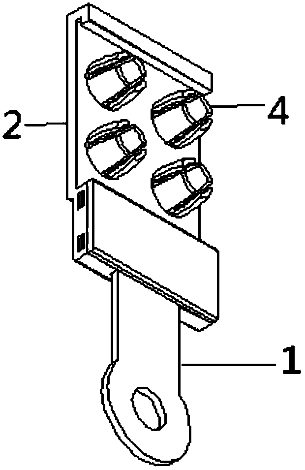
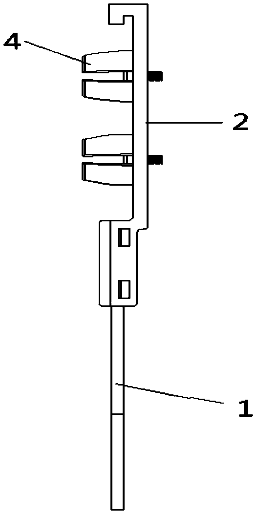
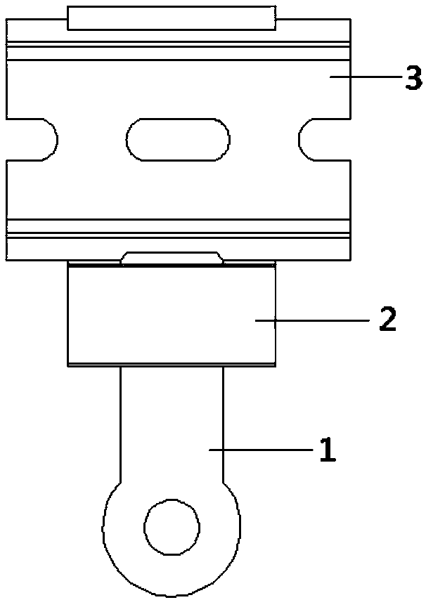
[0028] The core of the present invention is to provide a buckle device, which has a simple structure and low manufacturing cost, and at the same time can achieve the purpose of stable clamping effect and not easy to fail; another core of the present invention is to provide a buckle device with the above-mentioned buckle Electrical control equipment of the device.

[0029] In order to enable those skilled in the art to better understand the solution of the pres...


PUM


Abstract

The invention discloses a clamping buckle device of electrical control equipment. The clamping buckle device comprises a pull pin (1) and a clamping buckle body (2), wherein the clamping buckle body (2) is used for being clamped to a guide rail (3) on the two sides of the guide rail (3), the clamping buckle body (2) comprises a first clamping buckle part (21) used for being clamped to one side ofthe guide rail (3), and the clamping buckle body (2) further comprises a second clamping buckle part (22) which is clamped to the pull pin (1) and used for limiting the other side of the guide rail (3). The invention further discloses the electrical control equipment comprising the clamping buckle device. According to the clamping buckle device, by improving the connection structure of the pull pin and the second clamping buckle part, the structure that the pull pin is clamped to the second clamping buckle part is adopted, the relatively high cost caused by a complicated spring structure and replacement of the spring structure is avoided, the clamping structure is simple and easy to operate, the manufacturing cost is low, and the aims that the clamping effect is stable and clamping is notprone to failure can be achieved.

Description

technical field [0001] The invention relates to the technical field of automation control equipment, in particular to a buckle device. The invention also relates to an electrical control device with the buckle device. Background technique [0002] C-type guide rails are more and more commonly used in electrical control cabinets. The guide rails provide guidance, positioning and support for various electrical components. The common guide rails are C45 type guide rails. Various electrical components (such as air switches, contactors, terminal blocks, controllers, etc.) design, production and maintenance. [0003] The existing guide rail buckle is usually integrated with electrical components, and the controller shells produced in small batches need to process molds, which is costly and limits the use of C-type guide rails to a large extent. The existing independent guide rail buckle is a metal structure, which is directly connected with the controller by screws. The existin...

Claims


Application Information

Patent Timeline
Patent Type & Authority Applications(China)
IPC IPC(8): H05K7/14
CPCH05K7/1401H05K7/1415
Inventor 高洪兵徐德俊刘军杜文学王钦若
Owner GUANGDONG UNIV OF TECH
Why Eureka
Try Eureka