
Petroleum loading barrel convenient to transport

An oil and oil pumping technology, applied in the field of oil loading barrels that are easy to transport, can solve the problems of falling loading barrels, inconvenient oil extraction, easy oil shaking, etc.

Pending Publication Date: 2018-10-19
彭云秋
View PDF8 Cites 1 Cited by
  • Summary
  • Abstract
  • Description
  • Claims
  • Application Information

AI Technical Summary

Problems solved by technology

[0004] In order to overcome the shortcoming that when the general loading barrel is in the transportation process, the oil is easy to shake and cause the loading barrel to fall down, and it is not convenient to take out the oil, the technical problem is to provide a method that can limit the oil, and the oil is not easy to shake, and the oil is not easy to shake. Oil loading barrel that is easy to transport and easy to pump oil out without the barrel falling down

Method used


Image

  • Petroleum loading barrel convenient to transport
  • Petroleum loading barrel convenient to transport
  • Petroleum loading barrel convenient to transport

Examples


Embodiment 1

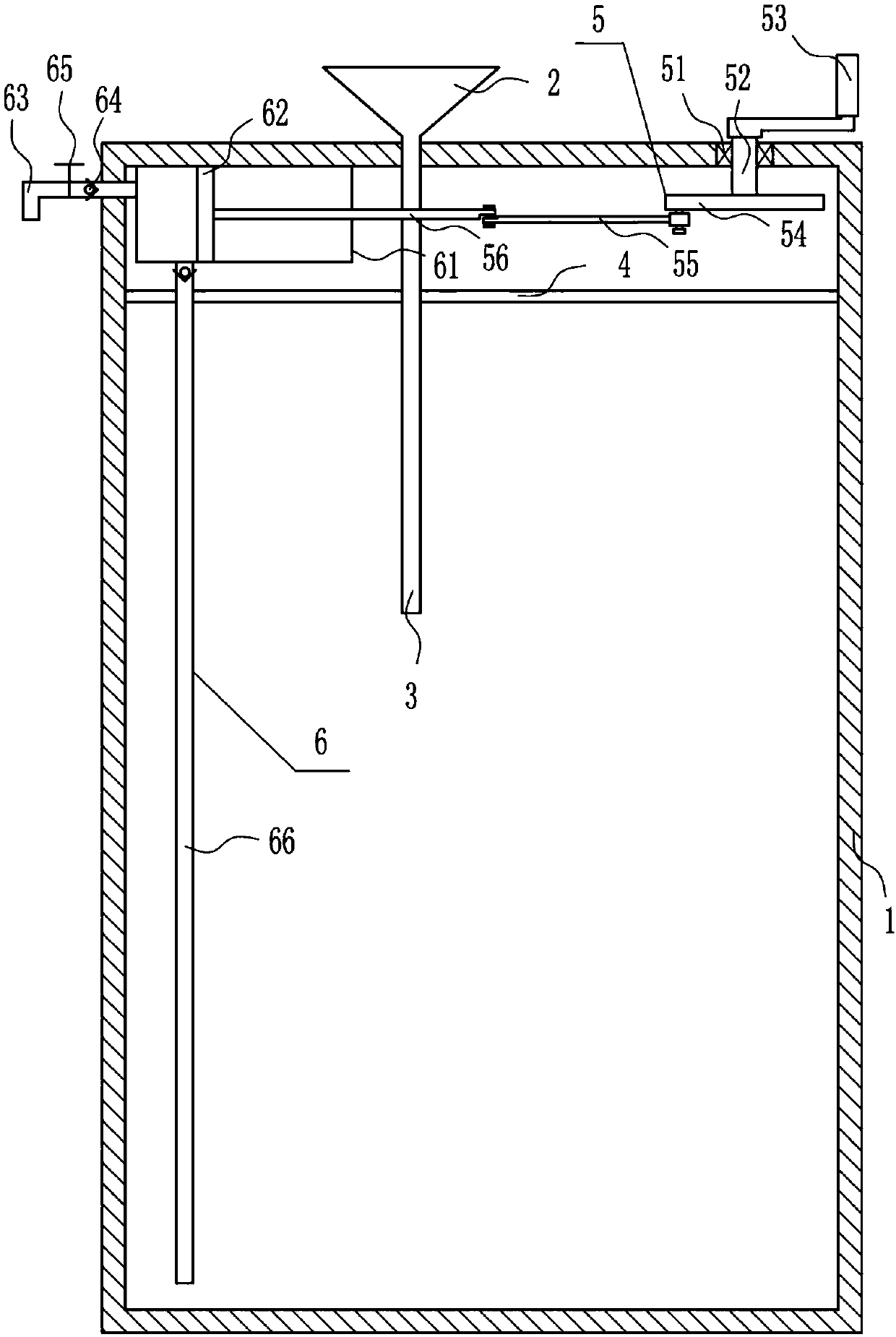
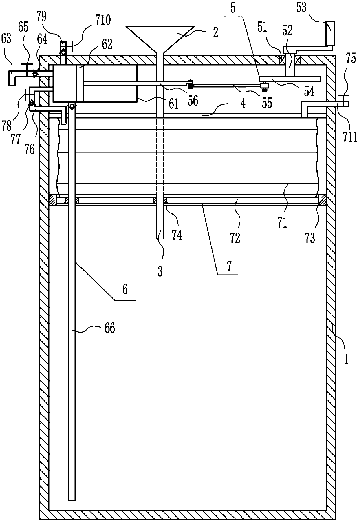
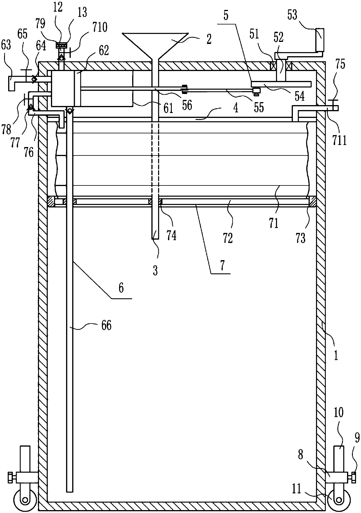
[0024] An oil-laden barrel for easy transport, such as Figure 1-3 As shown, it includes a loading barrel 1, a lower hopper 2, a lower material pipe 3, a partition 4, a manual device 5 and an oil pumping device 6, and a lower hopper 2 is installed on the left side of the top of the loading barrel 1, and the lower hopper 2 and the loading barrel 1 Internally connected, the bottom of the lower hopper 2 is connected to the lower material tube 3, the lower material tube 3 is connected to the lower hopper 2, the lower material tube 3 is located in the loading barrel 1, and the upper left side of the loading barrel 1 and the upper right side A partition 4 is installed between them, an oil pumping device 6 is arranged on the left side of the top of the loading barrel 1, and a manual device 5 is arranged on the right side of the top of the loading barrel 1, and the manual device 5 is connected with the oil pumping device 6.

Embodiment 2

[0026] An oil-laden barrel for easy transport, such as Figure 1-3 As shown, it includes a loading barrel 1, a lower hopper 2, a lower material pipe 3, a partition 4, a manual device 5 and an oil pumping device 6, and a lower hopper 2 is installed on the left side of the top of the loading barrel 1, and the lower hopper 2 and the loading barrel 1 Internally connected, the bottom of the lower hopper 2 is connected to the lower material tube 3, the lower material tube 3 is connected to the lower hopper 2, the lower material tube 3 is located in the loading barrel 1, and the upper left side of the loading barrel 1 and the upper right side A partition 4 is installed between them, an oil pumping device 6 is arranged on the left side of the top of the loading barrel 1, and a manual device 5 is arranged on the right side of the top of the loading barrel 1, and the manual device 5 is connected with the oil pumping device 6.

[0027] The manual device 5 includes a bearing seat 51, a ro...

Embodiment 3

[0029] An oil-laden barrel for easy transport, such as Figure 1-3 As shown, it includes a loading barrel 1, a lower hopper 2, a lower material pipe 3, a partition 4, a manual device 5 and an oil pumping device 6, and a lower hopper 2 is installed on the left side of the top of the loading barrel 1, and the lower hopper 2 and the loading barrel 1 Internally connected, the bottom of the lower hopper 2 is connected to the lower material tube 3, the lower material tube 3 is connected to the lower hopper 2, the lower material tube 3 is located in the loading barrel 1, and the upper left side of the loading barrel 1 and the upper right side A partition 4 is installed between them, an oil pumping device 6 is arranged on the left side of the top of the loading barrel 1, and a manual device 5 is arranged on the right side of the top of the loading barrel 1, and the manual device 5 is connected with the oil pumping device 6.

[0030] The manual device 5 includes a bearing seat 51, a ro...


PUM


Abstract

The invention relates to a petroleum loading barrel, in particular to a petroleum loading barrel convenient to transport. The petroleum loading barrel convenient to transport can limit petroleum, thepetroleum can not shake easily, the petroleum loading barrel is not prone to falling down, and the petroleum can be extracted out conveniently. According to the technical scheme, the petroleum loadingbarrel convenient to transport comprises a loading barrel body and the like; a feeding hopper is mounted on the left side of the top of the loading barrel body, and communicates with the internal ofthe loading barrel body; the bottom end of the feeding hopper body is connected with a feeding pipe; the feeding pipe communicates with the internal of the feeding hopper; the feeding pipe is positioned in the loading barrel; and a separation plate is mounted between the upper part of the left side surface and the upper part of the right side surface in the loading barrel. A petroleum extracting device can extract out the petroleum, so that operators can collect the petroleum conveniently; and a limiting device can limit the petroleum, so that the petroleum is not likely to shake and avoid falling of the loading barrel, and the effects of limiting the petroleum, enabling the petroleum not to shake, enabling the loading barrel not to fall down and facilitating extracting of petroleum are achieved.

Description

technical field [0001] The invention relates to an oil loading drum, in particular to an oil loading drum which is convenient for transportation. Background technique [0002] Petroleum, one of the main objects of geological exploration, is a viscous, dark brown liquid known as the "blood of industry." There are oil reserves in parts of the upper crust. The main component is a mixture of various alkanes, naphthenes and aromatic hydrocarbons. [0003] After the oil has been processed, it needs to be packed into the loading barrel for transportation, and when the general loading barrel is in the transportation process, the oil is easy to shake and cause the loading barrel to fall, which will cause the oil to easily leak or even explode. The oil in the loading barrel is not convenient for taking out the oil, so it is urgent to develop a kind of oil loading barrel that can limit the oil, and the oil is not easy to shake, and the loading barrel is not easy to fall down, and it ...

Claims


Application Information

Patent Timeline
Patent Type & Authority Applications(China)
IPC IPC(8): B65D25/02B65D25/38B65D25/42B65D1/12
CPCB65D25/02B65D1/12B65D25/38B65D25/42
Inventor 彭云秋文璋
Owner 彭云秋
Learn More