A high-efficiency floating oil suction device for jet cleaning of oil storage tanks

A suction device and oil storage tank technology, applied in the field of jet cleaning, can solve problems such as difficult extraction, manual adjustment, time-consuming and labor-intensive problems

Active Publication Date: 2020-07-07
HEFEI GENERAL MACHINERY RES INST +1
View PDF7 Cites 0 Cited by
  • Summary
  • Abstract
  • Description
  • Claims
  • Application Information

AI Technical Summary

Problems solved by technology

The original suction device only has a suction elbow with a flat mouth, and the position between the nozzle and the bottom of the tank must be manually adjusted during installation, which is time-consuming and laborious
And during the suction operation, because the oil floats on the water surface, most of the liquid extracted from the nozzle is water, only a small amount of oil slick, and a large amount of slick oil still remains in the tank, making it difficult to extract

Method used


Image

  • A high-efficiency floating oil suction device for jet cleaning of oil storage tanks
  • A high-efficiency floating oil suction device for jet cleaning of oil storage tanks
  • A high-efficiency floating oil suction device for jet cleaning of oil storage tanks

Examples


Embodiment Construction

[0031] Below in conjunction with embodiment technical solution of the present invention is made more specific description:

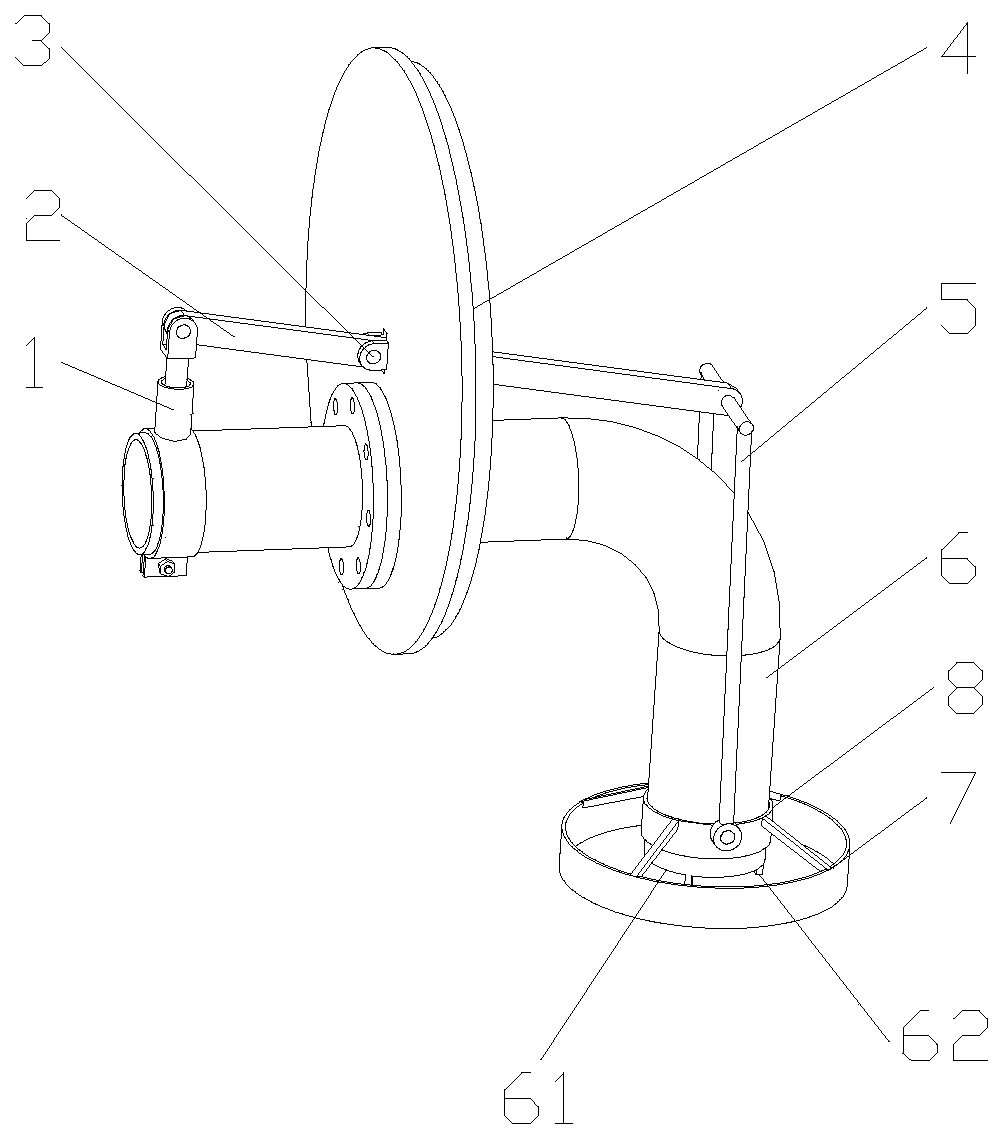
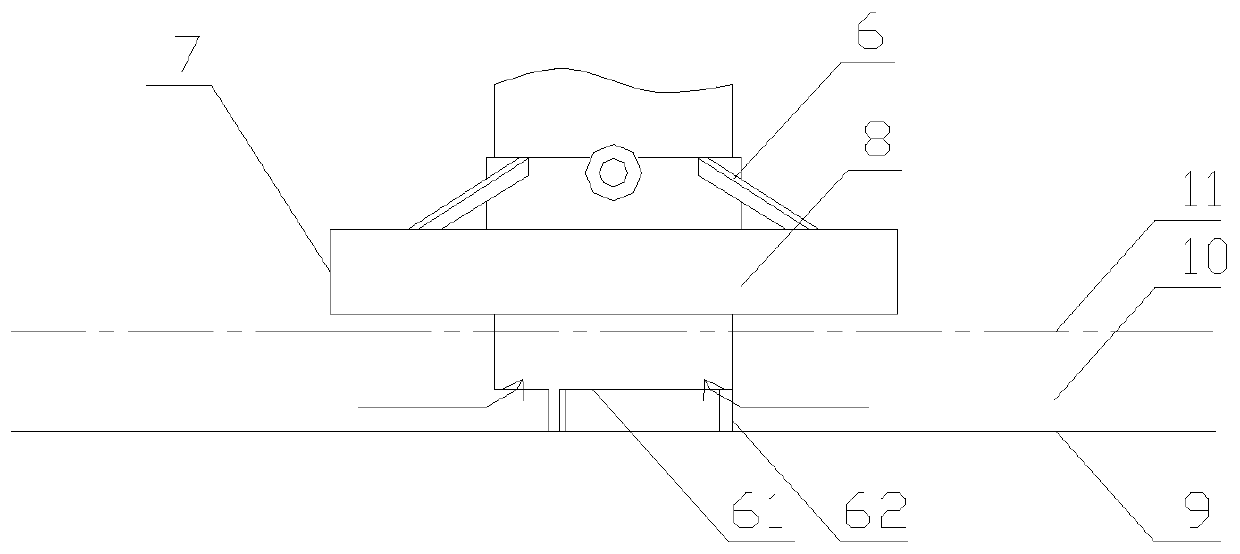
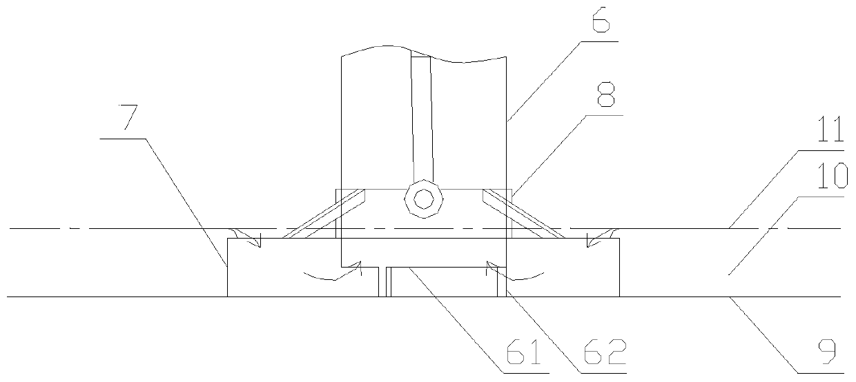
[0032] Such as figure 1 As shown: the present invention includes a suction elbow 6 and an annular water-repelling and oil-repellent weir 7, the suction port 61 of the suction elbow 6 is arranged toward the bottom of the oil storage container, and the suction port 61 is connected to the oil storage container There is a space between the bottoms to form a fluid channel, and the gap between the water-blocking and oil-repellent weir 7 is set outside the suction port 61; the water-blocking and oil-repellent weir 7 is driven by the driving mechanism to move upward to realize the The water-blocking and oil-repelling weir 7 is lifted relative to the bottom of the oil storage container, or the water-blocking and oil-repelling weir 7 is driven to move downward by the driving mechanism to realize that the water-blocking and oil-repelling weir 7 is lowered relative ...


PUM


Abstract

The present invention relates to a high-efficiency oil slick suction device for oil storage tank jet cleaning. The high-efficiency oil slick suction device comprises a suction elbow and an annular water blocking oil repellent weir, the suction opening of the suction elbow is arranged towards the bottom of an oil storage container, a space for formation of a fluid channel is reserved between the suction opening and the bottom of the oil storage container, the annular water blocking oil repellent weir is disposed outside the suction opening; the water blocking and oil repellent weir is driven upward by a driving mechanism to realize the fact that the water blocking and oil repellent weir is uplifted from the bottom of the oil storage container, or the water blocking and oil repellent weir isdriven downward by the driving mechanism to realize the fact that the water blocking and oil repellent weir is fallen down to the bottom of the oil storage container. By the act that the water blocking and oil repellent weir is fallen down to the bottom of the oil storage container, an upper liquid level, namely an oil slick layer, in the oil storage container is preferentially sucked, and the oil slick can be efficiently sucked.

Description

technical field [0001] The invention belongs to the field of jet cleaning, in particular to a high-efficiency floating oil suction device for jet cleaning of oil storage tanks. Background technique [0002] The most common storage equipment for crude oil reserves is large oil storage tanks. Before 2005, the 3 The following storage tanks are mainly used, and then 100,000 m 3 The above is the main one. Due to the composition and characteristics of crude oil, the generation of oil tank bottom sludge is inevitable, and the amount is large (generally 2.5% of the tank capacity). Such a large amount of sludge deposits cannot be used, which not only wastes energy but also reduces the effective storage capacity. Moreover, since the storage tank has a necessary inspection cycle of 6 years, the sludge must be removed and the tank wall cleaned for inspection and inspection. How to clean up and recycle these sludges has always been a difficult project. The traditional manual cleaning...

Claims


Application Information

Patent Timeline
Patent Type & Authority Patents(China)
IPC IPC(8): B08B3/02
CPCC02F1/40
Inventor 曲玉栋巴胜富王永强庞雷陈正文鲁飞韩彩红苏吉鑫张的朱华清周连春
Owner HEFEI GENERAL MACHINERY RES INST
Why Eureka
Try Eureka