multi-channel injector

A jet and multi-channel technology, applied in the field of negative pressure suction equipment, can solve the problems of low nozzle bearing pressure, non-adjustable nozzle, twisted orifice, etc., achieve good cleaning performance, simplify the structure, and increase the bearing pressure.

Active Publication Date: 2016-05-04
GP ENTERPRISES CO LTD
View PDF5 Cites 0 Cited by
  • Summary
  • Abstract
  • Description
  • Claims
  • Application Information

AI Technical Summary

Problems solved by technology

[0003] For the nozzles in the existing ejector, if the nozzles are clogged, use a soft brush or toothpick to clean it and be very careful during the cleaning process, which may distort the orifice. In addition, the existing nozzles have low bearing pressure and low efficiency. At the same time, The spout is not adjustable

Method used


Image

  • multi-channel injector

Examples


Embodiment

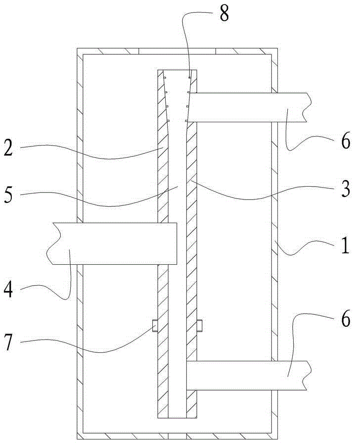
[0017] The multi-channel ejector of the present embodiment, such as figure 1 As shown, it includes a jet box 1 with an outlet. The jet box 1 is provided with a left splint 2 and a right splint 3 that fit each other. The center of the left splint 2 is provided with a jet liquid inlet that passes through the left splint 2 and is perpendicular to the left splint. Tube 4, jet liquid inlet The inlet end of the tube 4 is connected to the outside of the jet box 1 .

[0018] Between the left splint 2 and the right splint 3, a plurality of jet nozzles 5 communicated with the jet liquid inlet pipe 4 are formed, and the plurality of jet nozzles 5 are evenly distributed along the center circumference of the jet liquid inlet pipe 4, and the aperture of each jet nozzle 5 is 8-20mm, the outlet end of each jet nozzle 5 is set opposite to the outlet of the jet box 1, and the edge of the right splint 3 is provided with an air inlet pipe 6 communicating with each jet nozzle 5.

[0019] In this ...


PUM


Abstract

The invention relates to a multi-channel jet device and belongs to the technical field of jet pumps utilizing pumped fluid inertia for pumping fluid. The multi-channel jet device comprises a jet box provided with an outlet, a left clamping plate and a right clamping plate which are attached to each other are arranged in the jet box, a jet liquid inlet pipe penetrating through the left clamping plate and perpendicular to the same is arranged at the center of the left clamping plate, an inlet end of the jet liquid inlet pipe is communicated with the outside of the jet box, a plurality of jet nozzles communicated with the jet liquid inlet pipe are made between the left clamping plate and the right clamping plate and are distributed around the jet liquid inlet pipe circumferentially and uniformly, the orifice diameter of each jet nozzle ranges from 8mm to 20mm, an outlet end of each jet nozzle is opposite to the outlet of the jet box, and gas inlet pipes communicated with each jet nozzle are arranged at the edge of the right clamping plate. The multi-channel jet device has the advantages of high bearing pressure and good cleaning performance.

Description

technical field [0001] The invention relates to a negative pressure suction device, which belongs to the technical field of jet pumps for pumping fluid by utilizing the inertia of the pumped fluid. Background technique [0002] Jet vacuum pump is a device that generates, improves and maintains vacuum in a closed space by mechanical, physical, chemical or physical and chemical methods. It is generally composed of three parts: submersible pump, ejector, and pump box. It is widely used in decompression evaporation, crystallization, distillation, drying, decolorization, deodorization, vacuum transportation, etc. in petroleum, chemical, food, pharmaceutical, light industry, environmental protection and other industries. In the process. [0003] For the nozzles in the existing ejector, if the nozzles are clogged, use a soft brush or toothpick to clean it and be very careful during the cleaning process, which may distort the orifice. In addition, the existing nozzles have low bear...

Claims


Application Information

Patent Timeline
Patent Type & Authority Patents(China)
IPC IPC(8): F04F5/46F04F5/10
Inventor 周长根候潇寒张薇华陆俊芳
Owner GP ENTERPRISES CO LTD
Why Eureka
Try Eureka