Highway bridge deck water drainage facility

A technology for drainage facilities and highway bridges, applied in bridge construction, bridges, bridge parts, etc., can solve problems such as difficult filter removal and cleaning, vehicle tires slipping, out of control, etc., and achieve the effect of convenient cleaning

Active Publication Date: 2018-10-19
QINGDAO INSTALLATION & CONSTR
View PDF6 Cites 4 Cited by
  • Summary
  • Abstract
  • Description
  • Claims
  • Application Information

AI Technical Summary

Problems solved by technology

[0002] As we all know, once water accumulates on the bridge deck of a highway bridge in a rainy day, the tires of vehicles traveling at high speed on it will be affected by the accumulation of water and cause slippage and loss of control, resulting in serious traffic accidents such as vehicle slippage or rollover. Drainage facilities are installed on the bridge deck to quickly remove the water on the bridge. The patent document No. 201720987455.6 provides a drainage facility for highway bridge decks. Clean up and drain the stagnant water, but in reality, when the stagnant water is too deep, when the staff needs to clean the filter screen deep in the stagnant water, it is difficult to take out the filter screen and clean it due to the resistance of the stagnant water , this is nothing more than increasing the difficulty of the work of the staff, so we propose a highway bridge deck drainage facility to solve the above problems

Method used


Image

  • Highway bridge deck water drainage facility
  • Highway bridge deck water drainage facility
  • Highway bridge deck water drainage facility

Examples


Embodiment

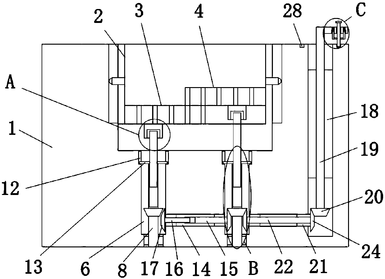
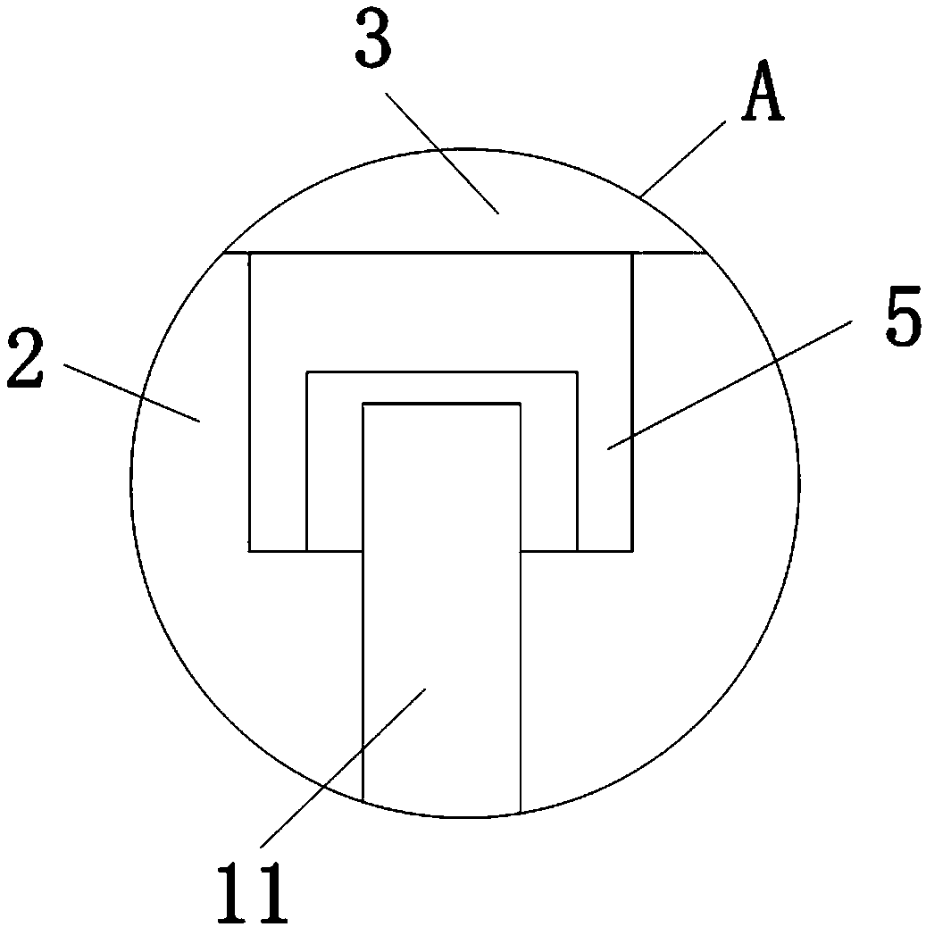
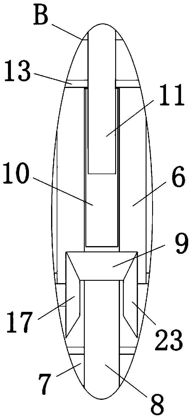
[0026] refer to Figure 1-5In this embodiment, a drainage facility for the bridge deck of a highway bridge is proposed, which includes a mounting base 1, a placement groove 2 is provided on the top of the mounting base 1, and a bottom filter screen 3 and a top filter screen 4 are placed in the placement groove 2. , both sides of the bottom of the filter screen 3 are fixedly equipped with a fixed block 5, the bottom of the fixed block 5 is provided with a first card slot 6, and the bottom inner wall of the placement slot 2 is provided with two first card slots 6, the first card slot The inner wall of the bottom of the 6 is provided with a turning groove 7, and the same turning column 8 is installed in the turning groove 7 and the first draw-in groove 6, and the outer fixed sleeve of the turning column 8 is provided with a first bevel gear 9, and the rotating column 8 The top is provided with a first threaded groove 10, and the direction of rotation of the two first threaded gro...


PUM


Abstract

The invention discloses a highway bridge deck water drainage facility. The highway bridge deck water drainage facility comprises a mounting seat; a placing groove is formed in the top of the mountingseat; two misplaced filtering nets sticking to each other are placed in the placing groove; fixing blocks are both fixedly mounted at the bottoms of the two filtering nets; first clamping grooves areformed in the bottoms of the fixing blocks; two first clamping grooves are formed in the internal wall of the bottom of the placing groove; rotating grooves are formed in the internal walls of the bottoms of the first clamping grooves; and the same rotating columns are rotationally mounted in the rotating grooves and the first clamping grooves. When a drainage pipeline is clogged and the filteringnets are inconvenient for working personnel to clean, the vertical distance between the two filtering nets is increased by using an adjusting handle so that the blocked filtering nets generate a water drainage space; and therefore, accumulated water on the deck can be rapidly drained; and meanwhile, by lifting the filtering nets, the filtering nets can be rapidly and conveniently lifted from themounting seat so that the cleaning of the filtering nets is made convenient.

Description

technical field [0001] The invention relates to the technical field of drainage facilities, in particular to a drainage facility for highway bridge decks. Background technique [0002] As we all know, once water accumulates on the deck of a highway bridge in a rainy day, the tires of vehicles traveling at high speed on it will be affected by the accumulation of water and slip and lose control, resulting in serious traffic accidents such as vehicle slippage or rollover. Drainage facilities are set on the deck of the bridge to quickly drain the water on the bridge. The patent document with the patent number of 201720987455.6 provides a drainage facility for the bridge deck of the highway bridge. Clean up and drain the stagnant water, but in reality, when the stagnant water is too deep, when the staff needs to clean the filter screen deep in the stagnant water, it is difficult to take out the filter screen and clean it due to the resistance of the stagnant water , this is noth...

Claims


Application Information

Patent Timeline
Patent Type & Authority Applications(China)
IPC IPC(8): E01D19/08
CPCE01D19/086
Inventor 陈云
Owner QINGDAO INSTALLATION & CONSTR
Why Eureka
Try Eureka