
Concrete vibrator

A vibrating rod and concrete technology, which is applied in the construction, building structure, construction material processing and other directions, can solve the problems of uneven concrete tamping, single vibrating rod structure, small vibration coverage area, etc., to prevent delamination Segregation phenomenon, space saving, short vibrating time effect

Pending Publication Date: 2018-10-19
衡阳泰源商砼有限公司
View PDF0 Cites 1 Cited by
  • Summary
  • Abstract
  • Description
  • Claims
  • Application Information

AI Technical Summary

Problems solved by technology

However, the existing vibrating rod has a single structure, and the area covered by its vibration is small, and the position of the vibrating rod needs to be constantly replaced, so that the concrete is not uniformly tamped, and air bubbles are easily generated
Moreover, if multiple vibrating rods are used to work at the same time, the phenomenon of layering and segregation of concrete aggregates will occur due to the difference in vibration amplitude; if only one vibrating rod is used, it needs to be constantly swapped and inserted. It takes a long time to use and wastes manpower and material resources

Method used


Image

  • Concrete vibrator
  • Concrete vibrator
  • Concrete vibrator

Examples


Embodiment

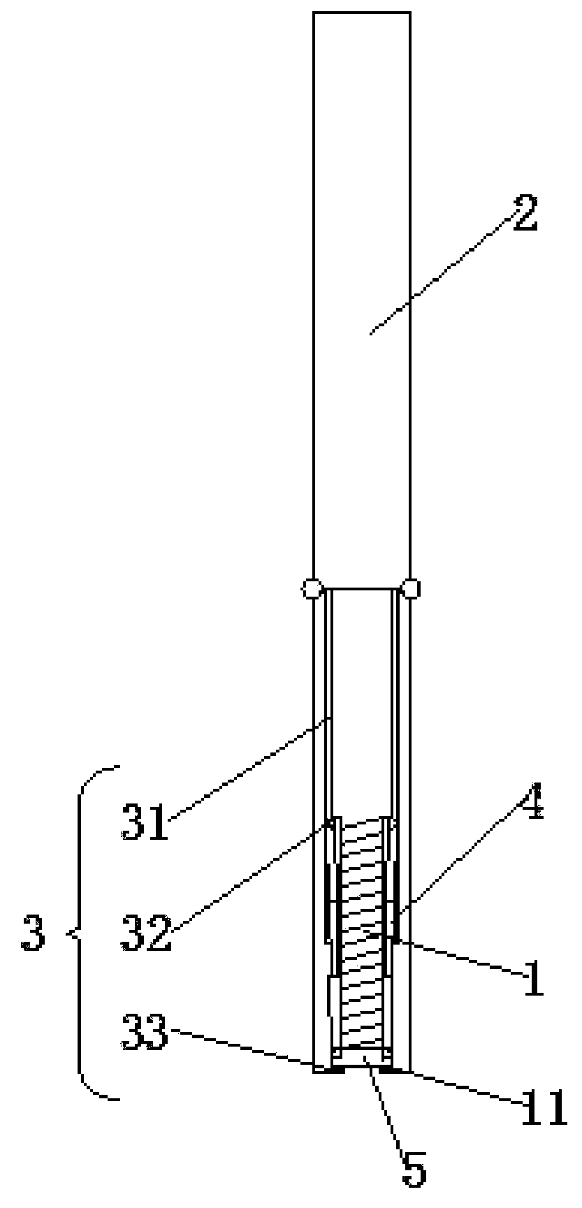
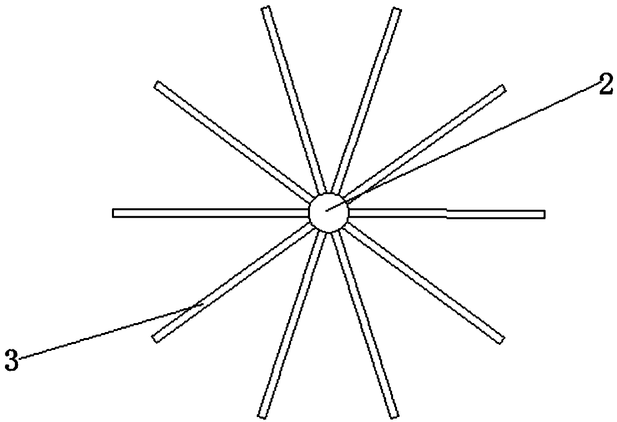
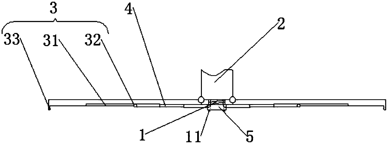
[0023] Embodiments of the present invention are as follows: Figure 1~4 As shown, a concrete vibrating rod includes a main rod 1, a sleeve 2 is sleeved on the main rod 1, and the end of the sleeve 2 away from the main rod 1 is provided so that the sleeve 2 can reciprocate along the axial direction of the main rod 1. The driving device of the movement, the other end of the sleeve 2 is hinged with at least two vibrating pieces 3, the side of the vibrating piece 3 close to the main rod 1 is provided with a guide rail 31, and the guide rail 31 is provided with a slider 32 that can slide along the guide rail 31, The slide block 32 is hinged with one end of a pole 4, and the other end of the pole 4 is hinged with the main rod 1. The invention is used for the improvement of the concrete vibrating rod, which can expand the vibrating area of ​​the vibrating rod, so that a larger area of ​​concrete can be simultaneously removed by the vibrating rod, and the overall vibrating time is sho...


PUM


Abstract

The invention discloses a concrete vibrator and belongs to the technical field of concrete equipment. The concrete vibrator is structurally characterized by comprising a main rod, wherein the main rodis sleeved with a sleeve; a drive device capable of enabling the sleeve to reciprocate in the axial direction of the main rod is arranged at the end, away from the main rod, of the sleeve; at least two vibration pieces are hinged to the other end of the sleeve; a guide rail is arranged on the side, close to the main rod, of each vibration piece, a slider capable of sliding along the guide rail isarranged on the guide rail, one end of the slider is hinged with one end of a support rod, and the other end of the support rod is hinged with the main rod. When used for vibrating concrete solids, the vibrator has the advantages that vibration area of the concrete can be increased, overall vibration time can be shortened, the concrete is more uniformly vibrated, and layering segregation is avoided.

Description

technical field [0001] The present invention relates to concrete equipment, and more particularly, to a concrete vibrator. Background technique [0002] At present, during the hardening process of concrete, in order to better remove the air bubbles mixed inside, it is necessary to insert a vibrator to remove the air inside by vibrating. Increase the density of concrete after hardening. However, the existing vibrating rod has a single structure, and the area covered by its vibration is small, and the position of the vibrating rod needs to be constantly replaced, so that the tamping of the concrete is uneven and air bubbles are easily generated. Moreover, if multiple vibrating rods are used to work at the same time, the phenomenon of layering and segregation of concrete aggregates will occur due to the difference in vibration amplitude; if only one vibrating rod is used, it needs to be constantly swapped and inserted. It takes a long time to use and wastes manpower and mater...

Claims


Application Information

Patent Timeline
IPC IPC(8): E04G21/08
CPCE04G21/08
Inventor 刘新岳
Owner 衡阳泰源商砼有限公司
Learn More