Powder Blank Forming Method

A blank forming and forming method technology, which is applied in the field of powder blank forming, can solve problems such as unevenness, uneven density gradient, and limited pressure capacity of transducers, so as to increase the vibration area, increase the contact area, and improve the blank. The effect of body density

Inactive Publication Date: 2020-01-17
沈阳赫声装备科技有限公司
View PDF5 Cites 0 Cited by
  • Summary
  • Abstract
  • Description
  • Claims
  • Application Information

AI Technical Summary

Problems solved by technology

Dry pressing is a kind of dry forming. Due to its high forming efficiency, precise size and low cost, it has become the preferred forming process for general structural ceramic products. However, due to its forming mechanism, there are always problems of density gradient and unevenness.
[0005] Therefore, some R&D personnel introduce ultrasonic vibration into the axial pressure rod, and apply vibration while the pressure rod is pressurized. To a certain extent, the internal equivalent stress distribution of the powder compact is more uniform, and the time required for the powder compact to be demoulded is reduced. The breakage of the compact due to the uneven distribution of internal stress reduces the loss of the compaction pressure along the axial direction and improves the density and uniformity of the powder compact. However, in the actual application process, there are the following problems: 1) In the extrusion rod Because the contact area between the pressing rod and the green body powder is too small, the ultrasonic vibration cannot be effectively and uniformly transmitted to the green body powder; 2) The ultrasonic vibration is gradually attenuated along the axial direction of the extrusion rod, and the density gradient and The problem of unevenness cannot be improved; 3) Applying vibration driving components on the extrusion rod makes the structure complex, the vibration mode is not reliable, and the efficiency is often low due to the limited pressure capacity of the transducer

Method used


Image

  • Powder Blank Forming Method
  • Powder Blank Forming Method

Examples


Embodiment 1

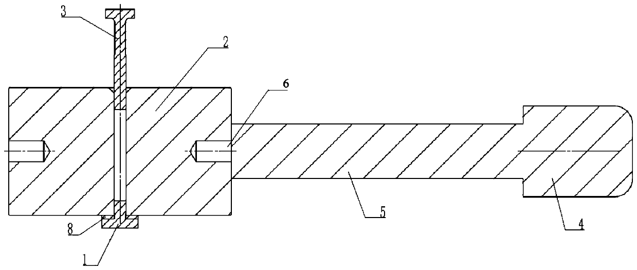
[0026] figure 1 Schematically shows the first embodiment of the structure of the powder blank forming device of the present invention, as figure 1 As shown, the powder billet molding device provided by the present invention includes: a bottom bracket 1, a mold 2, an extrusion rod 3, a transducer 4 and a horn 5, wherein the bottom bracket 1 and The molds 2 are flexibly connected by a rubber pad 8, and the bottom bracket 1 and the mold 2 form a mold cavity, and the rubber pad is provided to make the mold cavity more airtight; one end of the horn 5 and the mold 2 are connected through a bolt 6 Fixed connection, the other end of the horn 5 is bolted to the transducer 4; while the extrusion rod 3 exerts axial pressure on the powder, the transducer 4 receives the signal generated by the ultrasonic generator and converts electrical energy into mechanical energy. The vibration drives the horn 5, and the horn 5 drives the overall vibration of the mold 2, and the mold 2 evenly applies ...

Embodiment 2

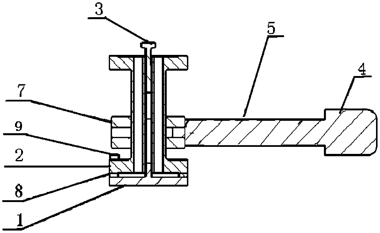
[0036] figure 2 Schematically shows the second embodiment of the structure of the powder blank forming device of the present invention, as figure 2As shown, the powder billet molding device provided by the present invention includes: a bottom bracket 1, a mold 2, an extrusion rod 3, a transducer 4, a horn 5, and the outer wall of the mold 2 The clamping device 7 on the top, the mold 2 and the horn 5 are indirectly connected through the clamping device 7; between the clamping device 7 and the horn 5 and between the horn 5 and the transducer 4 Both are connected by bolts; preferably, the clamping device 7 can be a clamp or the like.

[0037] Preferably, this embodiment is applicable to the case where the mold 2 is hollow and thin-walled. Since the thin-walled structure of the mold 2 itself is easily deformed by excitation, this embodiment drives the mold 2 to generate multiple shapes by combining the horn 5 and the clamping device. Modal compound vibration.

[0038] The mol...


PUM


Abstract

The invention discloses a powder billet forming device. The powder billet forming device comprises a die, an extruding rod, an amplitude-change pole and an energy converter, wherein the extruding rod is axially mounted in the die; one end of the amplitude-change pole is radially connected with the die, and the other end of the amplitude-change pole is connected with the energy converter; the electricity energy can be converted into mechanical vibration for driving the amplitude-change pole through the energy converter while axial pressure is applied to powder in the die through the extruding rod, and the die is driven to vibrate to apply radial pressure to the powder through the amplitude-change pole. The device is simple in structure, reliable in performance, and capable of quickly releasing the die; the powder is driven to vibrate through the die, so that the powder vibrating area is increased, and the powder can be uniformly vibrated, and as a result, the formed body density is improved, and the stress of the body is uniformly distributed. In addition, the invention also discloses a powder billet forming method.

Description

technical field [0001] The invention relates to the field of material processing and molding, in particular to a powder blank molding method. Background technique [0002] The main preparation process of powder metallurgy (Powder Metallurgy) and ceramic (Ceramic) includes powder preparation, blank forming and sintering. [0003] Compression molding is based on high pressure, which presses powdery blanks into block blanks in a mold. During the pressing process, the density, strength and pressure distribution in the green body will change due to the influence of external pressure on the billet. After the pressure is removed, the formed billet will be released from the die through the demoulding process, and then sintered after drying. [0004] Forming is to obtain a uniform and high-density green body material, which is an important link in powder metallurgy and ceramic preparation processes. Generally speaking, a green body with high uniformity, high density and near-net si...

Claims


Application Information

Patent Timeline
Patent Type & Authority Patents(China)
IPC IPC(8): B22F3/093
CPCB22F3/093
Inventor 孟宪林赵夙
Owner 沈阳赫声装备科技有限公司
Why Eureka
Try Eureka