Lens drive motor, camera and mobile terminal device

A lens driving and mobile terminal technology, which is applied in the field of cameras and mobile terminal devices, and lens driving motors, can solve the problems of difficult balance between driving force and linear stability

Pending Publication Date: 2018-10-19
SHANGHAI BILLU ELECTRONICS CO LTD
View PDF15 Cites 1 Cited by
  • Summary
  • Abstract
  • Description
  • Claims
  • Application Information

AI Technical Summary

Problems solved by technology

[0006] The main purpose of the present invention is to provide a lens drive motor, a camera and a mobile terminal device, so as

Method used


Image

  • Lens drive motor, camera and mobile terminal device
  • Lens drive motor, camera and mobile terminal device
  • Lens drive motor, camera and mobile terminal device

Examples


Embodiment 1

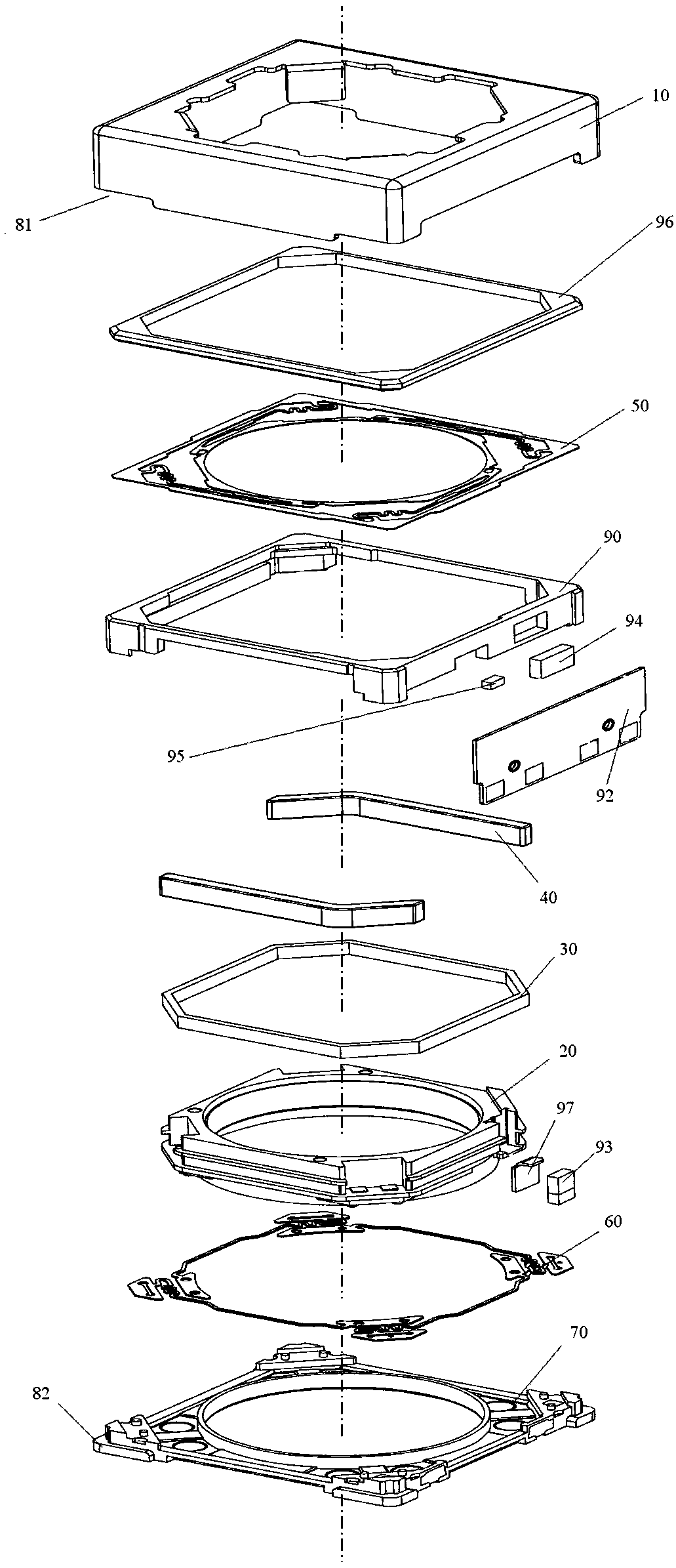
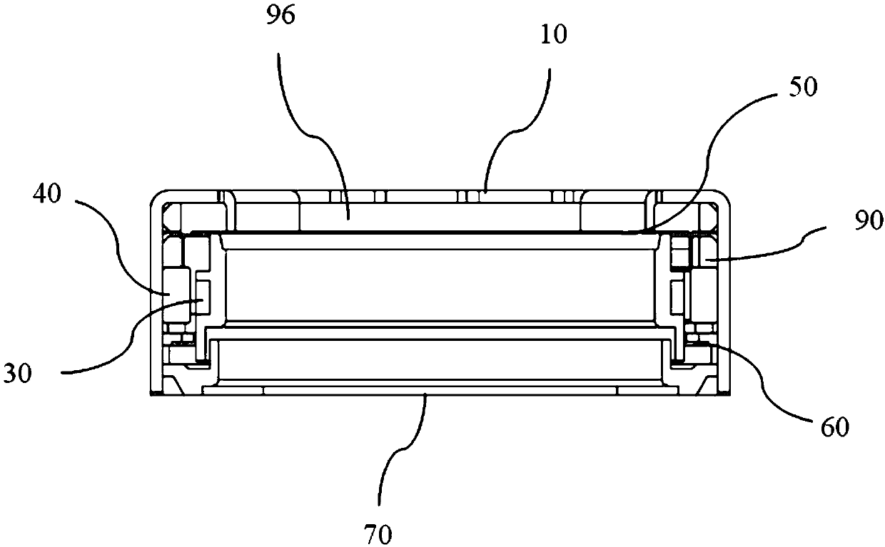
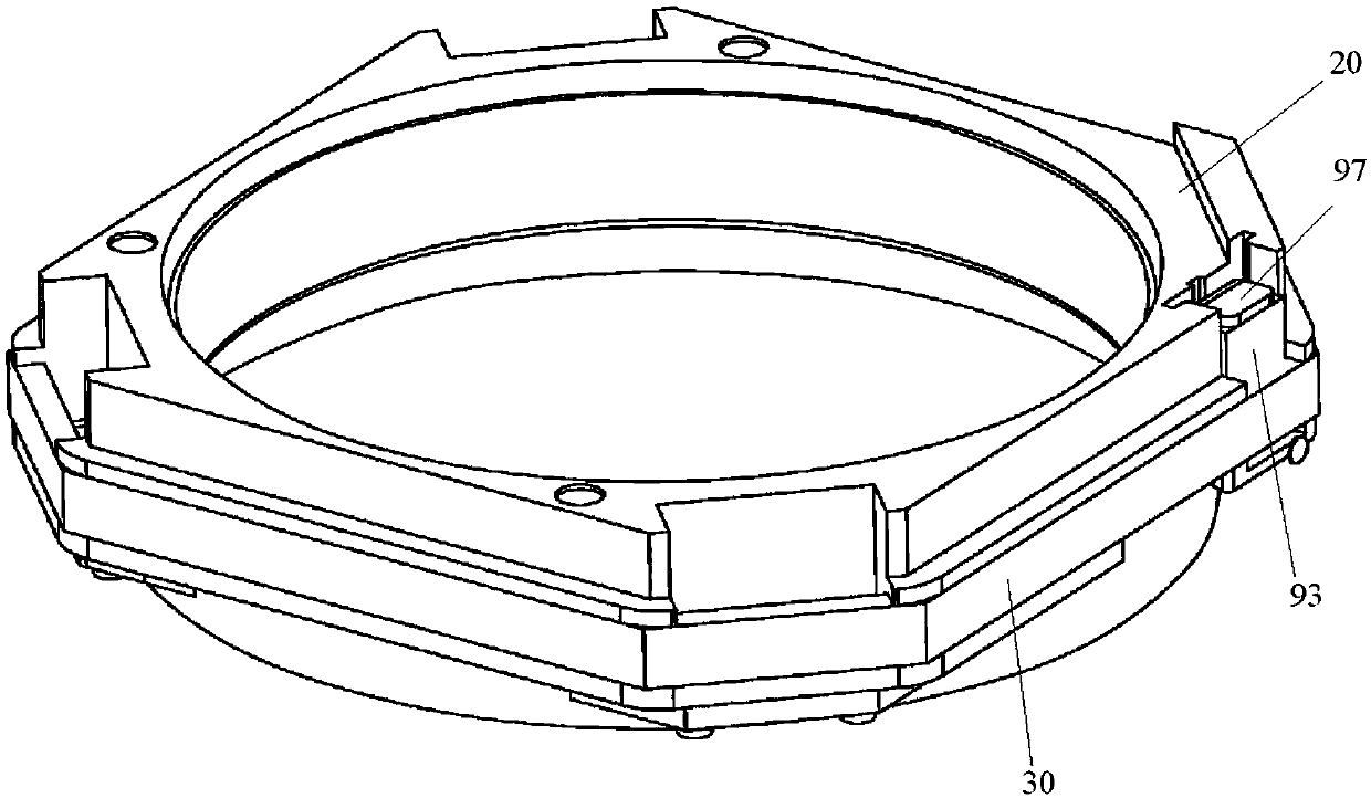
[0049] Such as Figure 1 to Figure 10 As shown, the lens driving motor includes a casing 10, a lens support body 20, a coil 30 and a magnet assembly 40. The coil 30 is wound on the lens support body 20 and is arranged in the casing 10. The magnet assembly 40 is arranged between the lens support body 20 and the casing. Between 10. The lens drive motor also includes a Hall chip 94, a Hall magnet 93 and a Hall gasket 97, the Hall chip 94 is arranged on the PCB board 92; the Hall magnet 93 is arranged on the lens support 20 corresponding to the Hall chip 94 on the position; the Hall gasket 97 is arranged between the Hall magnet 93 and the lens support body 20, and the Hall gasket 97 includes a back shield section 971 and a top shield section 972, and the top shield section 972 is formed by the back shield section 971. The top protrudes toward the PCB board 92 to cover the top of the Hall magnet 93 .

[0050] In this way, by setting the top shield section 972 on the Hall gasket 9...

Embodiment 2

[0068] The difference from the first embodiment is that the specific structure of the Hall pad 97 is different from that in the first embodiment.

[0069] Such as Figure 11 and Figure 12 As shown, the Hall spacer 97 also includes a bottom shielding section 973 , and the bottom shielding section 973 protrudes from the bottom of the back shielding section 971 to the PCB 92 to cover the bottom of the Hall magnet 93 . By setting the bottom shielding section 973, the magnetic field shielding effect can be further improved. This setup is perfectly reasonable as long as space within the lens drive motor allows.

[0070] Optionally, at least one of the top shielding section 972 and the bottom shielding section 973 is formed by bending. When the Hall gasket 97 only includes the back shielding section 971 , the top shielding section 972 and the bottom shielding section 973 , it is easier to obtain the desired shape of the Hall gasket 97 by bending and forming. Of course, the Hall ...

Embodiment 3

[0072] The difference from the second embodiment is that the specific structure of the Hall pad 97 is different from that of the second embodiment.

[0073] Such as Figure 13 and Figure 14 As shown, the Hall gasket 97 further includes a side shielding section 974 , and the side shielding section 974 protrudes from the side of the back shielding section 971 to the PCB 92 to cover the side of the Hall magnet 93 . By providing the side shielding section 974, the magnetic field shielding effect can be further improved. This setup is perfectly reasonable as long as space within the lens drive motor allows.

[0074] Optionally, at least one of the top shield segment 972, the bottom shield segment 973 and the side shield segment 974 is bent and formed. By bending and forming, it is easier to obtain the Hall gasket 97 of the desired shape. Of course, the Hall spacer 97 of the desired shape can also be obtained by metal casting.

[0075] When the Hall gasket 97 is manufactured b...


PUM


Abstract

The invention provides a lens drive motor, a camera and a mobile terminal device. The lens drive motor comprises a shell, a lens support body, a coil and a magnet assembly, wherein the coil is wound on the lens support body and is arranged in the shell, and the magnet assembly is arranged between the lens support body and the shell. The lens drive motor also comprises a Hall chip, a Hall magnet and a Hall gasket, wherein the Hall chip is arranged on a PCB (Printed Circuit Board); the Hall magnet is arranged on the lens support body in the position corresponding to the Hall chip; and the Hall gasket is arranged between the Hall magnet and the lens support body and comprises a back shielding section and a top shielding section, and the top shielding section extends from the top of the back shielding section to the PCB so as to cover the top of the Hall magnet. The lens drive motor provided by the invention solves the problem that the lens drive motor in the prior art has difficulty in balancing the driving force and the linear stability.

Description

technical field [0001] The present invention relates to the technical field of imaging equipment, in particular to a lens driving motor, a camera and a mobile terminal device. Background technique [0002] Since mobile terminal devices such as mobile phones generally require thinner and thinner structures, higher requirements are placed on the design of motors with a given external dimension, and it is difficult for thinner motors to generally meet various performance requirements. One of the obvious problems is that the thinner the motor design, the less power it tends to have to move the lens. [0003] On the other hand, in order to obtain high-definition image shooting effects, the requirements for camera lenses mounted on mobile phones and cameras are getting higher and higher. Currently, configuring larger lenses for cameras is a more direct and effective way to obtain high-definition images. . As we all know, the larger the mounted lens, the higher the driving force ...

Claims


Application Information

Patent Timeline
IPC IPC(8): G02B7/04G03B13/34H02K41/035
CPCH02K41/0356G02B7/04G03B13/34
Inventor 王建华龚高峰唐利新
Owner SHANGHAI BILLU ELECTRONICS CO LTD
Why Eureka
Try Eureka