An integrated system and method for oled stain detection and repair

A repair method and color spot technology, applied in static indicators, instruments, etc., can solve the problems of the multi-channel picture compensation effect not reaching the best, the color shift-like Mura compensation ability is poor, and the chromaticity shift cannot be evaluated. Reduce the impact of panel current limit, good compensation effect, and shorten the test cycle effect

Active Publication Date: 2022-02-18
WUHAN JINGCE ELECTRONICS GRP CO LTD
View PDF9 Cites 0 Cited by
  • Summary
  • Abstract
  • Description
  • Claims
  • Application Information

AI Technical Summary

Problems solved by technology

[0006] A. It takes a long time. Taking R / G / B each with 6 gray-scale images as an example, a total of 18 images need to be shot, and the low gray-scale brightness and low exposure time are longer;
[0007] B. Due to the current limitation of the OLED drive circuit, the current of a single-channel screen (R / G / B screen) and the current of a multi-channel screen (such as a white screen) are not simply superimposed or linear, and the R / G / B screen The IRDROP may be different from the IRDROP of the white picture, and the single-color picture can be compensated better by extracting the brightness for compensation alone, but the compensation effect of the compensation data for the multi-channel picture cannot be optimal;
[0008] C. Due to the existence of current limitation, the sum of the current values ​​of the RGB monochrome screen is greater than the current of the white screen, and the compensation of the monochrome screen cannot be equal to the compensation of the white screen, so the compensation ability for the color shift type Mura is poor, and it is impossible to evaluate before and after compensation. Chromaticity shift of

Method used


Image

  • An integrated system and method for oled stain detection and repair
  • An integrated system and method for oled stain detection and repair
  • An integrated system and method for oled stain detection and repair

Examples


Embodiment Construction

[0041]In order to make the object, technical solution and advantages of the present invention clearer, the present invention will be further described in detail below in conjunction with the accompanying drawings and embodiments. It should be understood that the specific embodiments described here are only used to explain the present invention, not to limit the present invention. In addition, the technical features involved in the various embodiments of the present invention described below can be combined with each other as long as they do not constitute a conflict with each other.

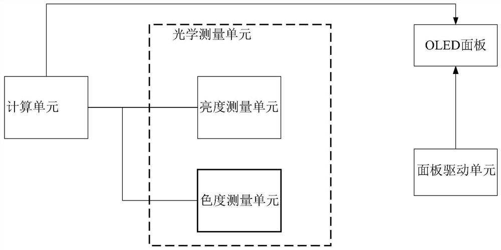
[0042] An embodiment of the OLED stain detection and repair integrated system provided by the present invention, its system refers to figure 1 , including a calculation unit, an optical measurement unit and a drive unit;

[0043] Among them, the optical measurement unit is connected with the calculation unit, and the driving unit acts on the OLED panel to be tested, and is used to drive the pane...


PUM


Abstract

The invention belongs to the technical field of panel detection, and discloses an integrated system and method for detecting and repairing OLED stains. The system includes a computing unit, an optical measuring unit, and a driving unit; the driving unit acts on the panel to drive it to light up different gray scales The white screen; the optical measurement unit is used to shoot the pixel brightness measurement picture and the chromaticity measurement picture of the panel under the white screen under the trigger of the drive unit; Brightness and chromaticity and determine the color spot type and level accordingly; and calculate the compensation data of each channel of R / G / B according to the brightness and chromaticity of each gray scale and convert it into a format acceptable to the driver chip of the panel and send it to the panel In the memory; under the control of the demura enable status register, the compensation data in the memory is called to repair the color spot on the panel to be repaired; the present invention reduces the test time by 2 / 3, greatly improves the work efficiency of color spot detection and compensation, and makes white The brightness uniformity of the picture is better compensated.

Description

technical field [0001] The invention belongs to the field of display technology, and more specifically relates to an integrated system and method for detecting and repairing OLED stains. Background technique [0002] Due to the limitations of the crystallization process, low-temperature polysilicon thin-film transistors (LTPS TFTs) fabricated on large-area glass substrates often have non-uniformity in electrical parameters such as threshold voltage and mobility. , this non-uniformity will be converted into current difference and brightness difference of OLED display device, and be perceived by human eyes, that is, mura (color spot) phenomenon. The mura repair technology is a technology that eliminates the mura phenomenon of the display and makes the brightness of the screen uniform. [0003] In the prior art, for example, a method for eliminating the Mura of an OLED display panel disclosed in Chinese patent application number 201610200089.5 first selects the corresponding c...

Claims


Application Information

Patent Timeline
Patent Type & Authority Patents(China)
IPC IPC(8): G09G3/00G09G3/3208
CPCG09G3/006G09G3/3208G09G2320/0626
Inventor 冯晓帆郑增强刘钊马尔威吴红君刘荣华沈亚非
Owner WUHAN JINGCE ELECTRONICS GRP CO LTD
Why Eureka
Try Eureka