New anti-overload safety motor

An anti-overload, new technology, applied in the direction of electrical components, electromechanical devices, electric components, etc., can solve problems such as motor installation is not smooth, easily damaged load equipment, fixing frame error, etc., to facilitate disassembly, inspection and maintenance, to ensure internal cleanliness, Simple and convenient cost-effective

Inactive Publication Date: 2018-10-19
张志通
View PDF0 Cites 6 Cited by
  • Summary
  • Abstract
  • Description
  • Claims
  • Application Information

AI Technical Summary

Problems solved by technology

The motor relies on electricity to generate a magnetic field, and generates mechanical power through the interaction of the magnetic field. When the load at the motor’s load end is too large or the load is damaged and stuck, the shaft will usually stop rotating due to the load problem, but the winding is still energized and powerful. If the electrical energy cannot be converted into kinetic energy in a timely manner, the motor will continue to heat up and burn itself out. The repair of the burned and damaged motor is complicated and costly. In addition, when the existing motor dissipates heat, the dust in the air will be brought into the interior and attached to the winding to affect the heat dissipation effect. It is easy to be damaged, and it is not convenient to extinguish the fire when the motor fails, and it is easy to damage other load equipment when it burns to the outer end, causing serious losses. At the same time, the installation and maintenance of the current motor is very inconvenient, and the preset fixing frame will have certain errors. As a result, the installation of the motor is not smooth, and the weight of the motor itself is too large. It is inconvenient to reverse during maintenance and inspection, which delays time and reduces work efficiency.

Method used


Image

  • New anti-overload safety motor
  • New anti-overload safety motor
  • New anti-overload safety motor

Examples


Embodiment Construction

[0025] Below in conjunction with accompanying drawing and specific embodiment the present invention is described in further detail:

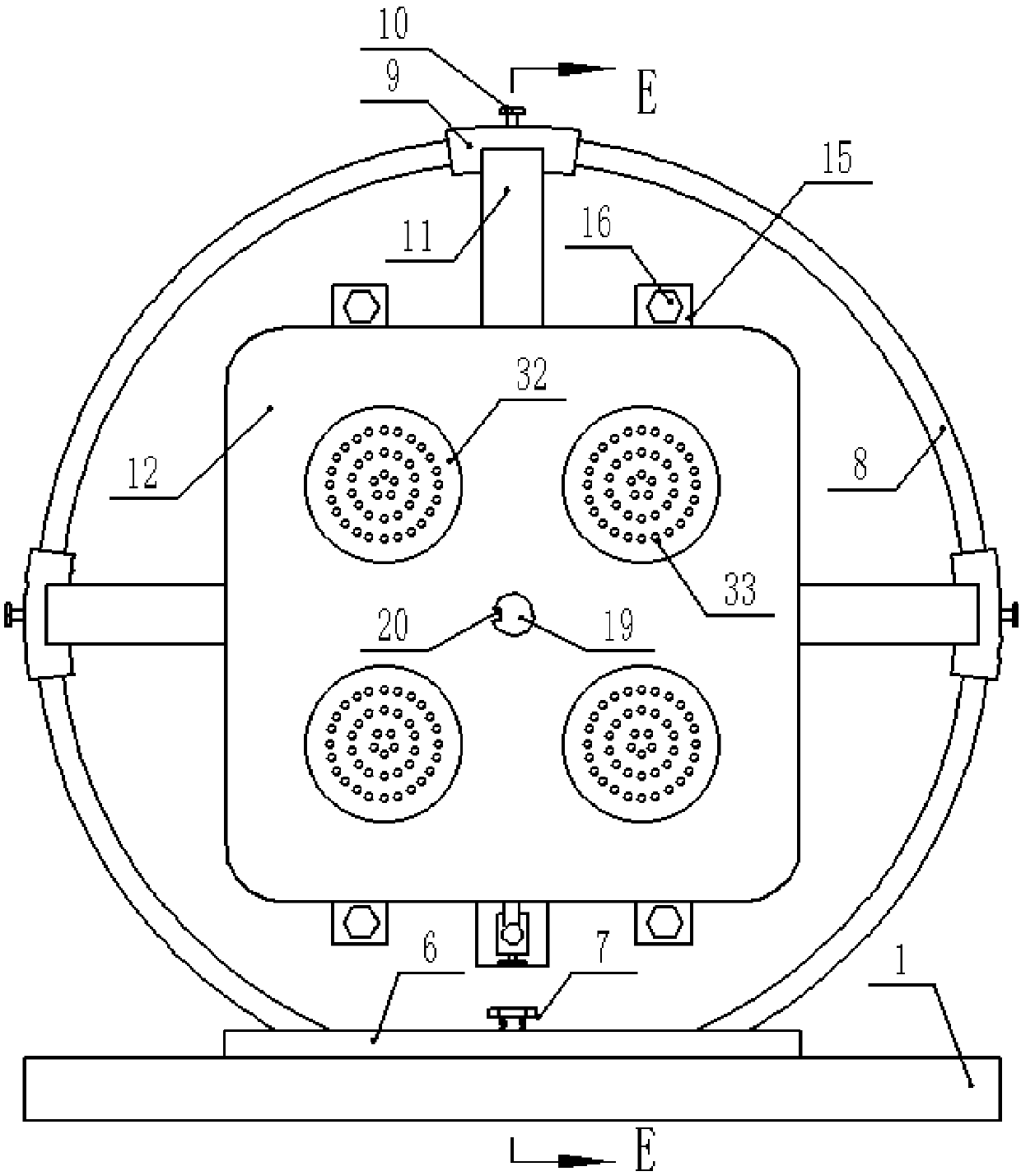
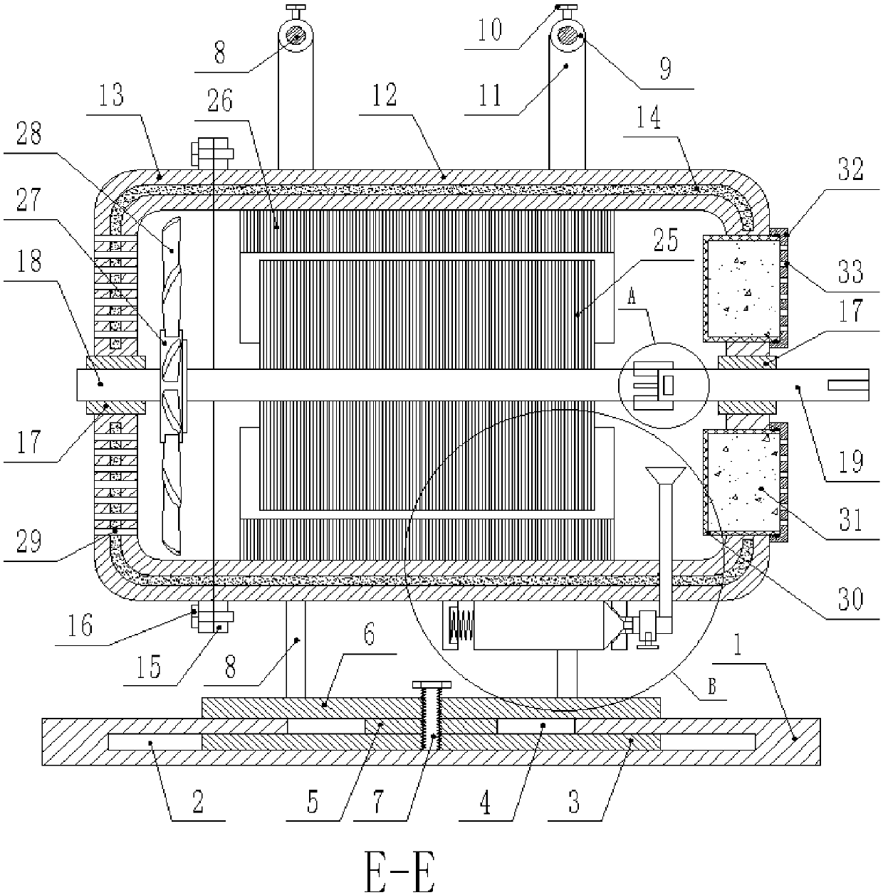
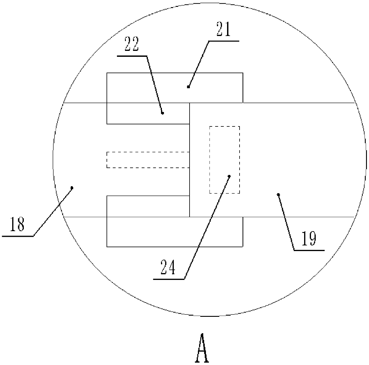
[0026] Such as Figure 1-Figure 6 As shown, a novel anti-overload safety motor includes a fixed plate 1, a circular cavity 2 is provided in the fixed plate 1, and a disc 3 slidingly connected with it is provided in the cavity 2, and the fixed plate 1 A round hole 4 corresponding to the disc 3 is provided in the middle of the upper end of the disc 3, a connecting plate 5 is fixed in the middle of the top of the disc 3, and a top plate 6 that fits with the top surface of the fixing plate 1 is fixed on the top of the connecting plate 5. The middle vertical thread of the top plate 6 is connected with the top plate bolts 7 passing through the connecting plate 5 and the disc 3, the top surface of the top plate 6 is fixed with a ring frame 8, and the ring frame 8 is covered with an arc-shaped sleeve 9 slidingly connected with it. , the arc-shaped slee...


PUM


Abstract

The invention discloses a new anti-overload safety motor, comprising a fixing plate, wherein the fixing plate is internally provided with a circular cavity, the cavity is internally provided a disk inslidable connection with the cavity, the middle of the upper end of the fixing plate is provided with a circular hole corresponding to the disk, a connecting plate is fixed at the middle of the top of the disk, the top of the connecting plate is fixed with a top plate attached to the top surface of the fixing plate, the middle of the top plate is vertically threaded with a top plate bolt passingthrough the connecting plate and the disk, the top surface of the top plate is fixed with an annular frame, the annular frame is sleeved with an arc-shaped sleeve slidably connected thereto, the arc-shaped sleeve is connected with a sleeve bolt for locking and fixing the sleeve, a fixing rod is fixed on the inner side of the sleeve bolt, and the lower end of the fixing rod is provided with a motorcasing fixedly connected thereto. When the front shaft of a motor stops rotating due to load problems, the strong torque can break ribs, and the serious consequences of the motor itself cannot be generated. The front shaft can be replaced for continuous use. The new ant-overload safety motor is simple, convenient, and low in cost.

Description

technical field [0001] The invention relates to the field of motors, in particular to a novel anti-overload safety motor. Background technique [0002] The motor is represented by the letter M (the old standard is D) in the circuit, and its main function is to generate driving torque as a power source for electrical appliances or various machinery. The motor relies on electricity to generate a magnetic field, and generates mechanical power through the interaction of the magnetic field. When the load at the motor’s load end is too large or the load is damaged and stuck, the shaft will usually stop rotating due to the load problem, but the winding is still energized and powerful. If the electrical energy cannot be converted into kinetic energy in a timely manner, the motor will continue to heat up and burn itself out. The repair of the burned and damaged motor is complicated and costly. In addition, when the existing motor dissipates heat, the dust in the air will be brought i...

Claims


Application Information

Patent Timeline
Patent Type & Authority Applications(China)
IPC IPC(8): H02K5/26H02K5/10H02K11/20A62C3/16
CPCH02K5/26A62C3/16H02K5/10H02K11/20
Inventor 张志通
Owner 张志通
Why Eureka
Try Eureka