
Insert for use in an injection molding nozzle and injection molding nozzle with such an insert

A technology for injection nozzles and inserts, applied in the field of inserts used in injection nozzles and injection nozzles with such inserts, to achieve the effects of saving energy costs, ensuring long-term use, and preventing peeling

Inactive Publication Date: 2018-10-23
GUENTHER HEISSKANALTECHNIK GMBH
View PDF2 Cites 2 Cited by
  • Summary
  • Abstract
  • Description
  • Claims
  • Application Information

AI Technical Summary

Problems solved by technology

In particular heat conduction to the injection mold or mold parts should be avoided

Method used


Image

  • Insert for use in an injection molding nozzle and injection molding nozzle with such an insert
  • Insert for use in an injection molding nozzle and injection molding nozzle with such an insert
  • Insert for use in an injection molding nozzle and injection molding nozzle with such an insert

Examples


Embodiment Construction

[0088] In the processing of thermosetting plastics and elastomer materials in which the plastic hardens under the influence of temperature, cold runner systems are used instead of hot runner systems. Therefore, when describing hot runner systems below, cold runner systems are always referred to, depending on the application and also according to the meaning.

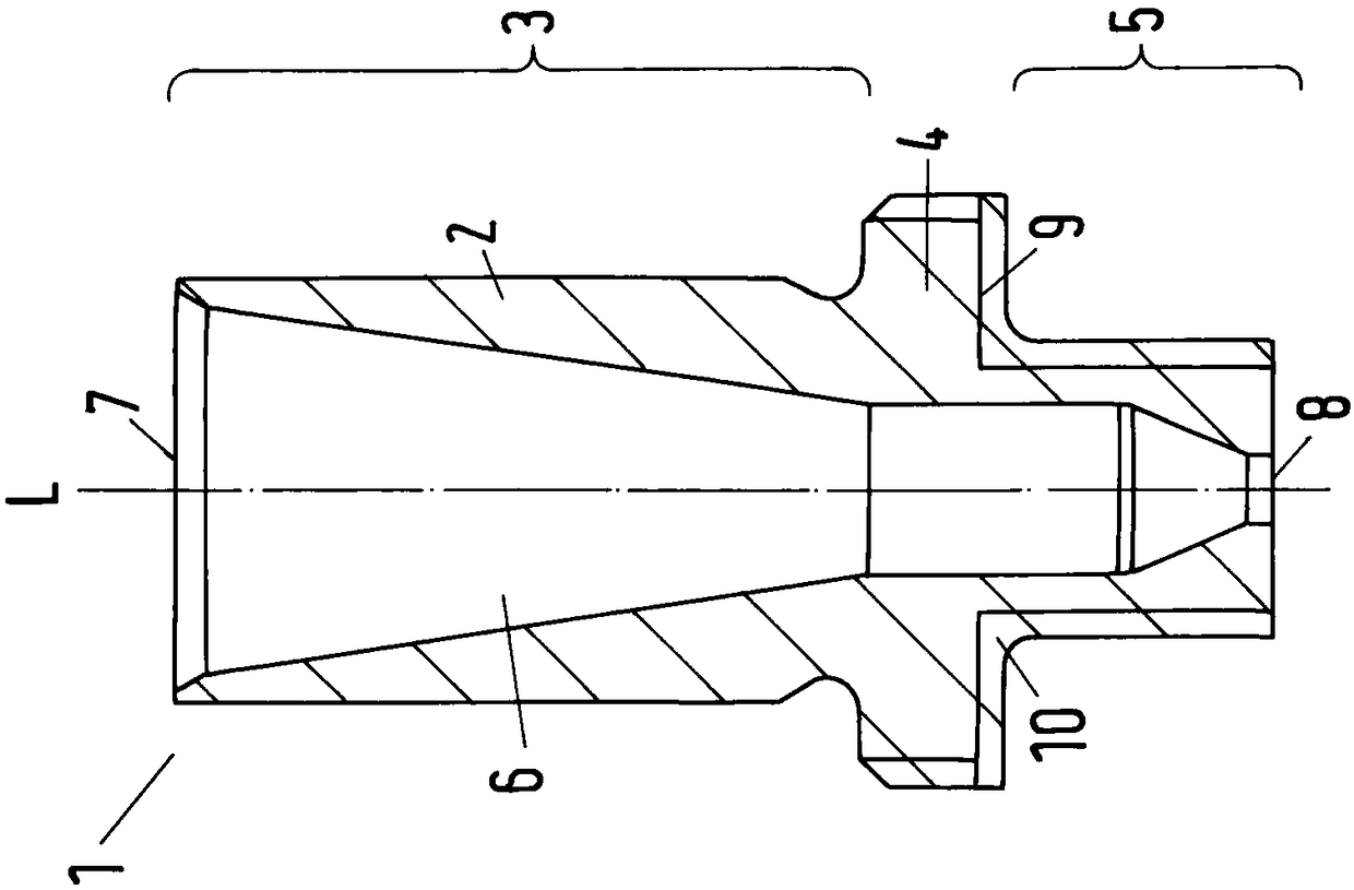
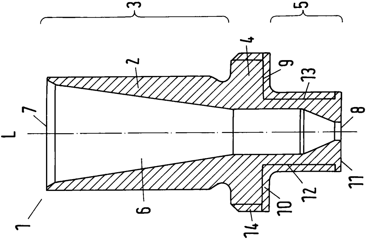
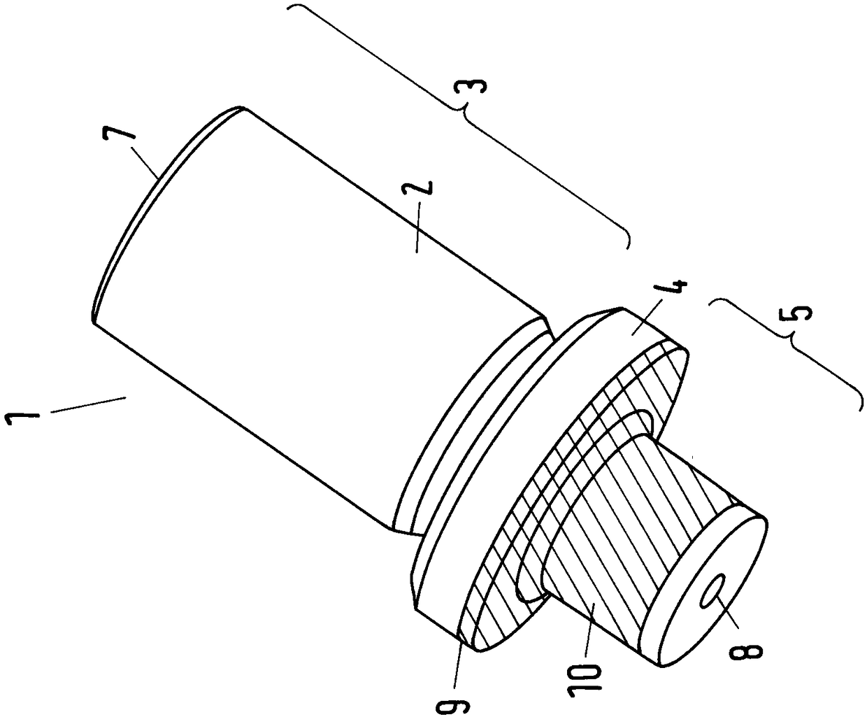
[0089] figure 1 with figure 2 Each shows a longitudinal section through an insert 1 according to the invention for an injection molding nozzle (not shown). The insert 1 is always formed by a corresponding insert body 2 made of a highly thermally conductive material. The insert body 2 here has a neck 3 , a collar 4 and an end 5 . The insert body 2 can be connected with its neck 3 to the injection molding nozzle, for example by being inserted or pushed onto the injection molding nozzle. The flange 4 protrudes radially relative to the neck 3 and the end 5 . The end portion 5 can be inserted into a cavity (not shown) o...


PUM


Abstract

The invention relates to an insert (1) for use in an injection molding nozzle, with an insert body (2) at least made from a high thermal conductivity material, in which at least one flow channel (6) is formed with an inlet opening (7) and an outlet opening (8), wherein the insert body (2) comprises a neck section (3), for joining to the injection molding nozzle, an end section (5), for inserting into a mold cavity of a mold insert, and a flange (4) with a stopping surface (9) projecting radially with respect to the end section (5), wherein the stopping surface (9) is formed on a surface of theradially projecting flange (4) facing the outlet opening (8). According to the invention, the stopping surface (9) and the end section (5) have at least partly an outer coating (10) made of a secondmaterial with a low thermal conductivity.

Description

technical field [0001] The invention relates to inserts for use in injection molding nozzles and injection molding nozzles for injection molds, which have an insert according to the invention. Background technique [0002] Injection molding nozzles, and especially hot runner nozzles, are inserted into injection molding molds in order to supply a flowable substance, such as plastic, at a predetermined temperature and high pressure to separable mold parts. They generally have material tubes with flow channels which are fluidly connected via inlets to distribution channels in the distribution plate and which lead via outlets to the outlets of the mold parts (cavities). [0003] All of the following embodiments relate not only to hot runner systems, but also to cold runner systems. [0004] In order to prevent the flowable material from cooling and solidifying in advance in the flow channel of the hot runner nozzle, a heating device is provided, which is sheathed or installed o...

Claims


Application Information

Patent Timeline
Patent Type & Authority Applications(China)
IPC IPC(8): B29C45/27B29C45/28
CPCB29C45/2711B29C45/28B29C2045/2766B29C2045/2777B29C2045/2787B29C2045/2798B29C45/278B29C2045/2785
Inventor H·君特S·索梅尔T·施内尔
Owner GUENTHER HEISSKANALTECHNIK GMBH
Learn More