
Strain monitoring method for surface bonding

A strain monitoring and curved surface technology, applied in the field of monitoring, can solve problems such as difficult optical degradation, birefringent optical characteristics of optical elements, and optical elements that cannot meet the needs, so as to reduce the process steps and improve the bonding effect

Active Publication Date: 2020-08-11
INTERFACE TECH CHENGDU CO LTD +2
View PDF12 Cites 0 Cited by
  • Summary
  • Abstract
  • Description
  • Claims
  • Application Information

AI Technical Summary

Problems solved by technology

If the bonding effect of the optical film is poor, the prepared optical element is prone to birefringence or other defects of optical property degradation, which cannot meet the application requirements
Although optical components with poor bonding effects can further use compensation films to improve the defects of optical characteristics, but optical degradation is difficult to detect visually, so optical components made by bonding curved surfaces often cannot meet the needs

Method used


Image

  • Strain monitoring method for surface bonding
  • Strain monitoring method for surface bonding
  • Strain monitoring method for surface bonding

Examples


Embodiment Construction

[0036] The making and using of embodiments of the invention are discussed in detail below. It should be appreciated, however, that the embodiments provide many applicable inventive concepts that can be embodied in a wide variety of specific contexts. The specific embodiments discussed are illustrative only and do not limit the scope of the invention.

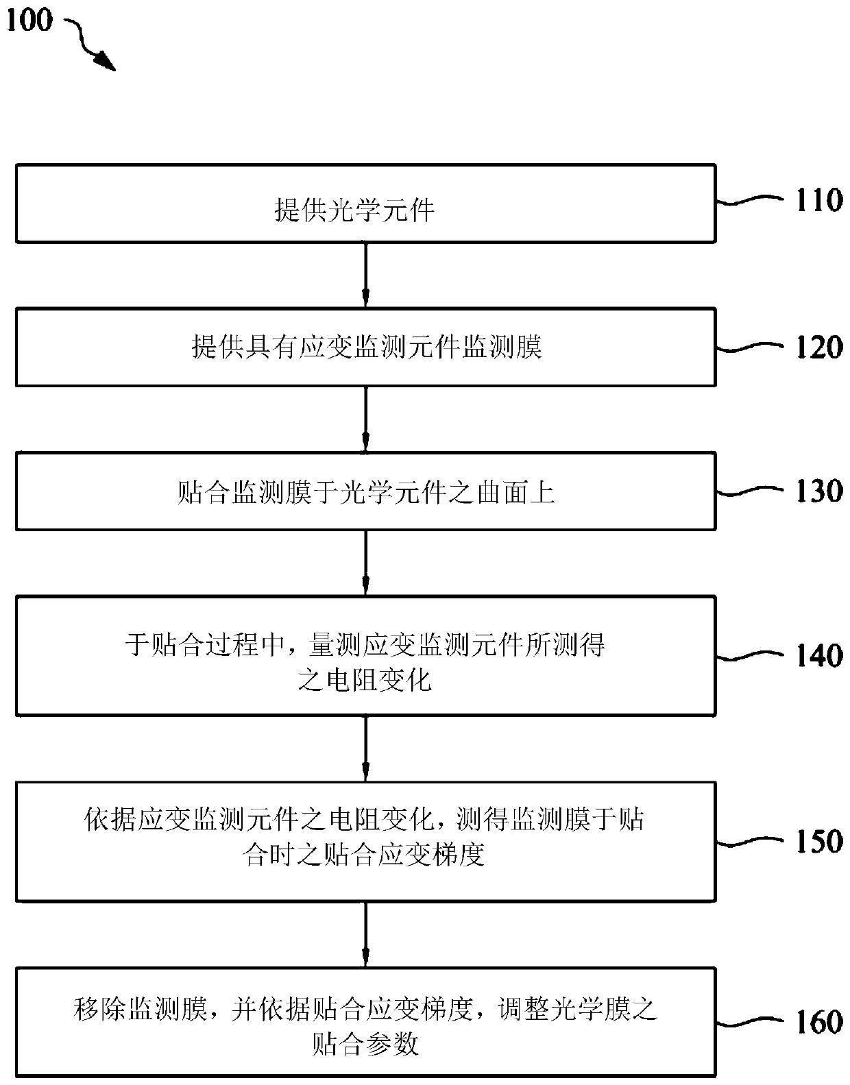
[0037] Please refer to figure 1 , which is a schematic flowchart illustrating a strain monitoring method for curved surface lamination according to an embodiment of the present invention. In the method 100 , the optical element and the monitoring film are provided first, as shown in operation 110 and operation 120 . Wherein, the optical element has a curved surface. In some embodiments, the curved surface of the optical element needs to be pasted with an additional optical film or other appropriate optical film to compensate the optical characteristics of the optical element, protect the curved surface of the optical element,...


PUM


Abstract

The invention relates to a curved surface fitting strain monitoring method. The method comprises the steps: pasting a monitoring film on a curved surface so as to measure pasting strain gradient; obtaining the strain change when the optical film is pasted and the parameters when the pasting can be adjusted, thereby improving the curved surface pasting effect. The pasting strain gradient is measured by a plurality of strain monitoring elements of the monitoring film.

Description

technical field [0001] The present invention relates to a monitoring method, and in particular provides a monitoring method capable of measuring the bonding strain gradient of curved surface bonding. Background technique [0002] Optical elements (such as optical lenses or optical films, etc.) are generally combined with multi-layer optical layers, so that the prepared optical elements have specific optical characteristics and can meet application requirements. Ordinary optical components can be adjusted in their materials during production, or directly injection-molded into optical components with multilayer optical films, so that they have the required optical properties. However, the optical element prepared by this method can only be applied to a single device, and the arrangement of each optical film cannot be flexibly adjusted, thus limiting its application range. [0003] In order to improve the above-mentioned defects of limited application, optical elements are gen...

Claims


Application Information

Patent Timeline
Patent Type & Authority Patents(China)
IPC IPC(8): G01B11/16
CPCG01B11/16
Inventor 赖世伦
Owner INTERFACE TECH CHENGDU CO LTD
Features
  • Generate Ideas
  • Intellectual Property
  • Life Sciences
  • Materials
  • Tech Scout
  • Unparalleled Data Quality
  • Higher Quality Content
  • 60% Fewer Hallucinations
Learn More