
A synchronous control system architecture to improve energy efficiency

A technology of synchronous control and system architecture, applied in the direction of cell structure combination, secondary battery repair/maintenance, electrical components, etc., can solve the problem of not being able to enter the power saving mode

Active Publication Date: 2021-06-08
广东广晟通信技术有限公司
View PDF6 Cites 0 Cited by
  • Summary
  • Abstract
  • Description
  • Claims
  • Application Information

AI Technical Summary

Problems solved by technology

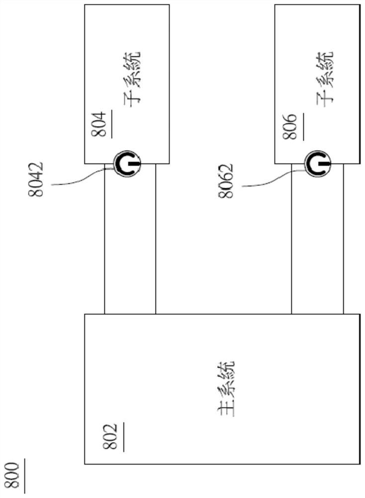
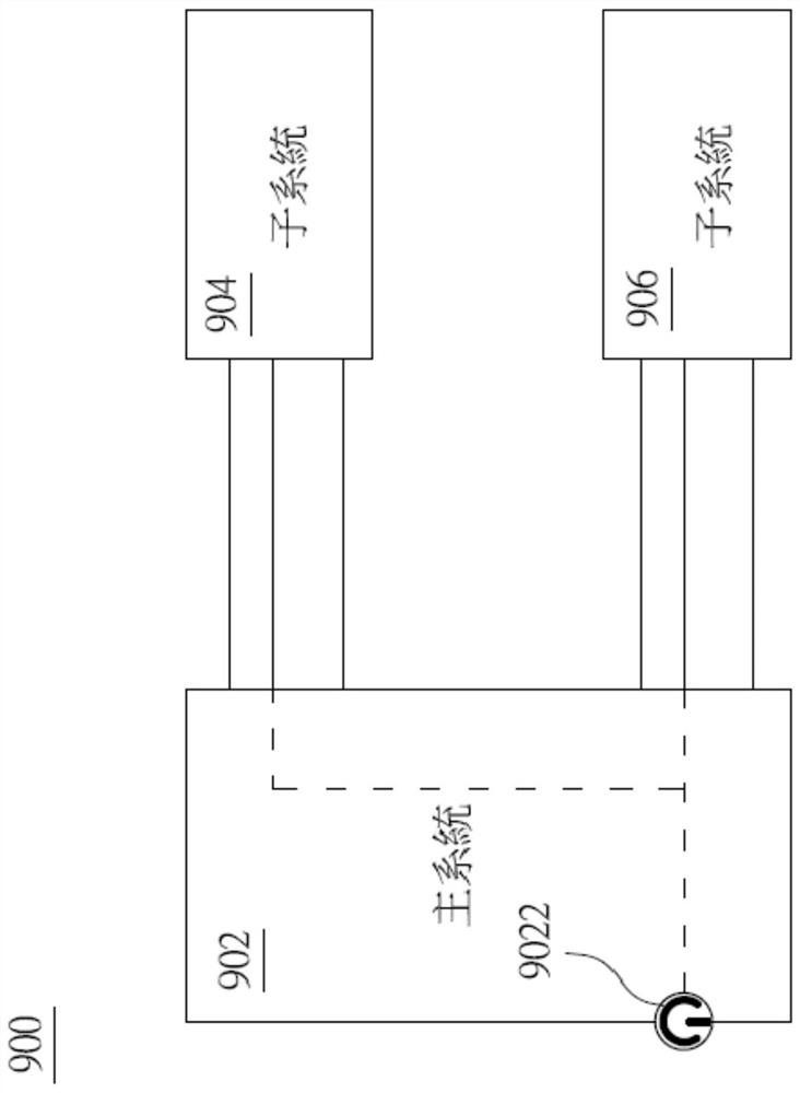
Although the main system 902 can remotely control the opening or closing of the first power supply subsystem 904 and the second power supply subsystem 906 through the switch 9022, the first power supply subsystem 904 and the second power supply subsystem 906 need to be in the working mode for a long time. To wait to receive the control signal sent by the main system 902 at any time, therefore, cannot enter the power saving mode
[0007] In summary, the existing master-slave architecture system has room for improvement, especially in communication and real-time monitoring, and it is urgent to improve the above shortcomings

Method used


Image

  • A synchronous control system architecture to improve energy efficiency
  • A synchronous control system architecture to improve energy efficiency
  • A synchronous control system architecture to improve energy efficiency

Examples


Embodiment Construction

[0027] Referring now in detail to the preferred embodiments of the synchronous control system disclosed in the present invention, examples of synchronous control systems are also provided in the following description. Exemplary embodiments of the synchronous control system disclosed in this disclosure are described in detail, but will be apparent to those skilled in the relevant art, and some features not particularly important to understanding the synchronous control system may not be shown for the sake of clarity .

[0028] In addition, it should be understood that the synchronous control system disclosed in the present invention is not limited to the detailed embodiments described below, and those skilled in the art can make various changes and modifications to them without departing from the spirit or scope of synchronous control and protection . For example, devices and / or features of different illustrative embodiments may be combined with each other and / or substituted f...


PUM


Abstract

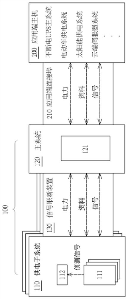
The present invention provides a synchronous control system framework for improving energy saving efficiency, which includes a main system and at least one power supply sub-system, the main system includes a power consumption analysis module; Communication between the main system, the power supply subsystem includes: at least one battery module and a power supply processing module; the power supply processing module is electrically connected to the battery module and is configured to receive a detection signal of the battery module and according to the detection The test signal confirms the battery status of the battery module, and then sends it to the power consumption analysis module of the main system for analysis; wherein the main system sends a feedback signal to the power supply processing module for processing according to the battery status. Thus, the main system remotely monitors the battery status of multiple subsystems in real time, and the power switch authority of each subsystem is controlled by firmware to achieve smart energy management.

Description

technical field [0001] The invention relates to the technical field of energy-saving control of multi-system serial connection, especially a kind of energy-saving control, which does not require hardware switches, and the main system can communicate with multiple subsystems through firmware to obtain battery information, so as to control the synchronization of multiple subsystems remotely and synchronously Control system architecture. Background technique [0002] Today, with the continuous advancement of science and technology, the demand for energy has risen rapidly in recent years, and energy solutions such as nuclear energy, hydropower, solar energy, wind power, and biomass energy have gradually been widely discussed by all walks of life. However, most of the renewable energy mentioned above is related to climate and environment, and the problem of unstable power supply has yet to be solved. Therefore, the electric energy storage system can not only assist the power pla...

Claims


Application Information

Patent Timeline
Patent Type & Authority Patents(China)
IPC IPC(8): H01M10/42
CPCH01M10/4207H01M10/425H01M2010/4271H01M2010/4278Y02E60/10
Inventor 邱文丰刘文广魏伟强兰洪春
Owner 广东广晟通信技术有限公司
Learn More