
Tool-cabinet-included power drawer cabinet with function selective delocking

An optional, drawer technology, applied in the direction of electrical components, pull-out switch cabinets, switchgear, etc., can solve problems such as messy, damaged parts, inconvenient parts and tools to find, etc., to achieve convenient use, simple structure, and provide The effect of using efficiency

Inactive Publication Date: 2018-10-23
丁大良
View PDF8 Cites 1 Cited by
  • Summary
  • Abstract
  • Description
  • Claims
  • Application Information

AI Technical Summary

Problems solved by technology

[0002] In general power supply drawer cabinets, each drawer assembly of the drawer cabinet is equipped with a locking device. However, most of the single drawer assemblies of the drawer cabinets are manually controlled mechanical locks. One side of the lock is used to control the fastening or loosening of the relative position of the lock to achieve the purpose of opening or closing. In use, the staff needs to carry multiple keys at the same time, which is not very practical and safe. In addition, the traditional electric drawer The items placed inside are messy, including various parts that need to be replaced, as well as the tools used to replace the parts. In actual use, due to the messy placement of the items, it is very inconvenient to find the parts and tools, and the parts and tools are mixed together. Tools can damage parts during pulling

Method used


Image

  • Tool-cabinet-included power drawer cabinet with function selective delocking
  • Tool-cabinet-included power drawer cabinet with function selective delocking
  • Tool-cabinet-included power drawer cabinet with function selective delocking

Examples


Embodiment Construction

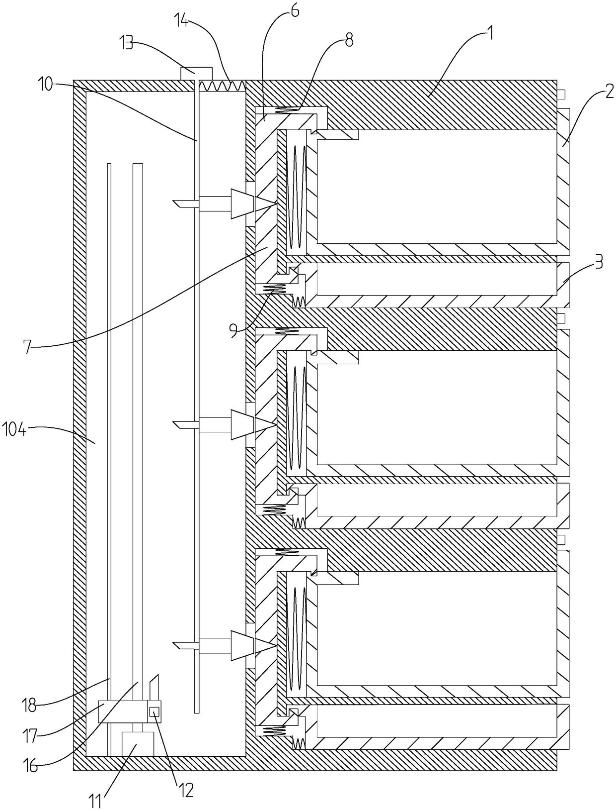
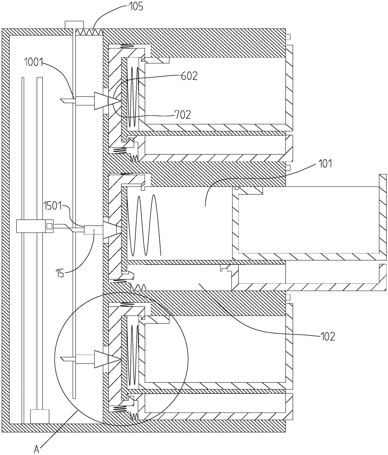
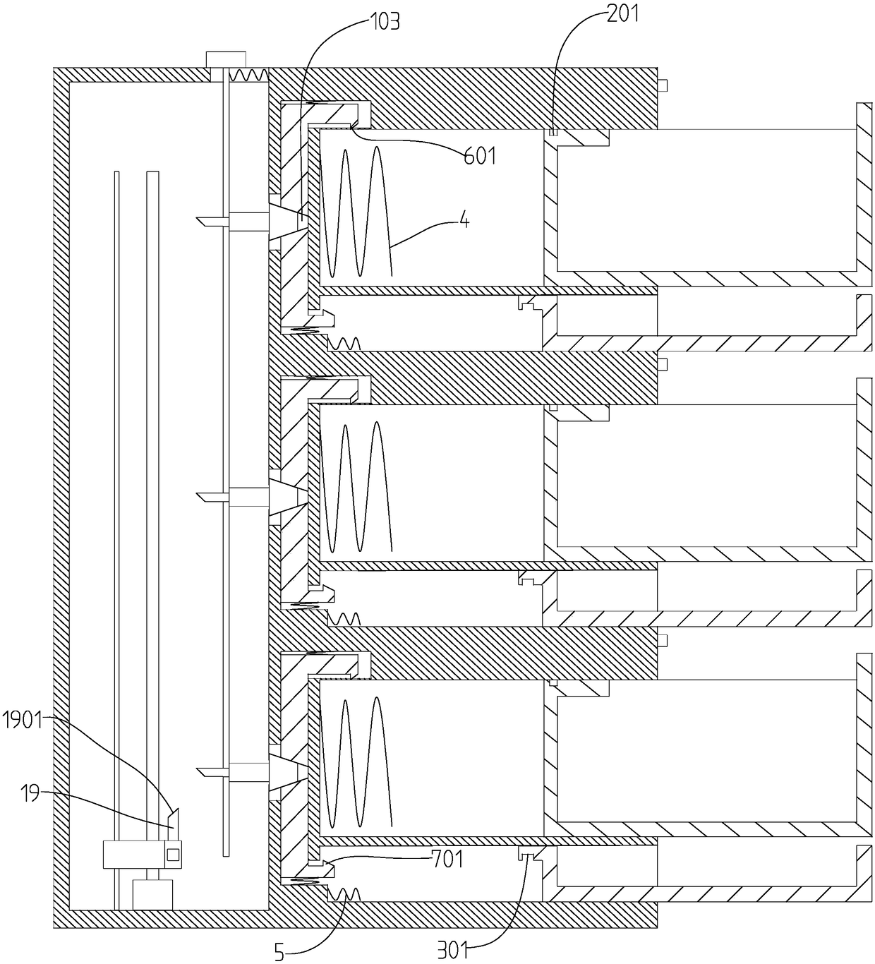
[0025] see Figure 1-4 As shown, a selectively unlockable power drawer cabinet with a tool cabinet includes a cabinet body 1, and three power drawer modules are sequentially arranged in the cabinet body 1 from top to bottom, and the power drawer module includes a power drawer 2 and a tool drawer 3, the cabinet body 1 is provided with three horizontally arranged drawer chutes 101 and tool chutes 102 from top to bottom, wherein the tool chutes 102 are located below the drawer chutes 101 , the power drawer 2 and the tool drawer 3 are slidably connected in the drawer chute 101 and the tool chute 102 respectively; The spring 4, the fourth spring 5 that forces the tool drawer 3 to move to the right is provided in the tool chute 102 .

[0026] The left end of the drawer chute 101 in the cabinet body 1 is vertically provided with a lock block chute 103 communicating with the drawer chute 101 and the tool chute 102 , and inside the lock block chute 103 A first oblique hook lock block...


PUM


Abstract

The invention discloses a tool-cabinet-included power drawer cabinet with the function selective delocking. The power drawer cabinet comprises a cabinet body; and a plurality of power drawer modules are arranged in the cabinet body successively from top to bottom. The power drawer modules consist of power drawers and tool drawers. Besides, a plurality of drawer chutes and tool chutes are formed inside the cabinet body successively from top to bottom; and the power drawers and the tool drawers are arranged in the drawer chutes and tool chutes in sliding connection. Locking block chutes are formed in the left ends of the drawer chutes in the cabinet body; first inclined hook locking blocks for locking the power drawers and second inclined hook locking blocks for locking the tool drawers arearranged in the locking block chutes in sliding connection. In addition, a delocking module for controlling opening or closing of the power drawer modules is also arranged in the cabinet body. The power drawer cabinet having a simple structure is used conveniently; and no key is needed. Because of separate setting of the power drawers and tool drawers, the usage efficiency of the power drawer cabinet is improved substantially.

Description

technical field [0001] The invention relates to the technical field of electric drawer cabinets, in particular to a selectively unlockable electric drawer cabinet with a tool cabinet. Background technique [0002] In general power supply drawer cabinets, each drawer assembly of the drawer cabinet is equipped with a locking device. However, most of the single drawer assemblies of the drawer cabinets are manually controlled mechanical locks. One side of the lock is used to control the fastening or loosening of the relative position of the lock to achieve the purpose of opening or closing. In use, the staff needs to carry multiple keys at the same time, which is not very practical and safe. In addition, the traditional electric drawer The items placed inside are messy, including various parts that need to be replaced, as well as the tools used to replace the parts. In actual use, due to the messy placement of the items, it is very inconvenient to find the parts and tools, and t...

Claims


Application Information

Patent Timeline
Patent Type & Authority Applications(China)
IPC IPC(8): H02B11/133
CPCH02B11/133
Inventor 丁大良
Owner 丁大良
Learn More