Single-side guide pillar mould base
A technology of guide pillars and mold bases, applied in metal processing equipment, forming tools, manufacturing tools, etc., can solve the problems of reducing the stability of the overall mechanism and lack of fixed parts, and achieve the effect of easy replacement and improved stability
- Summary
- Abstract
- Description
- Claims
- Application Information
AI Technical Summary
Problems solved by technology
Method used
Image

Examples
Embodiment Construction
[0011] The present invention is described below in conjunction with accompanying drawing.
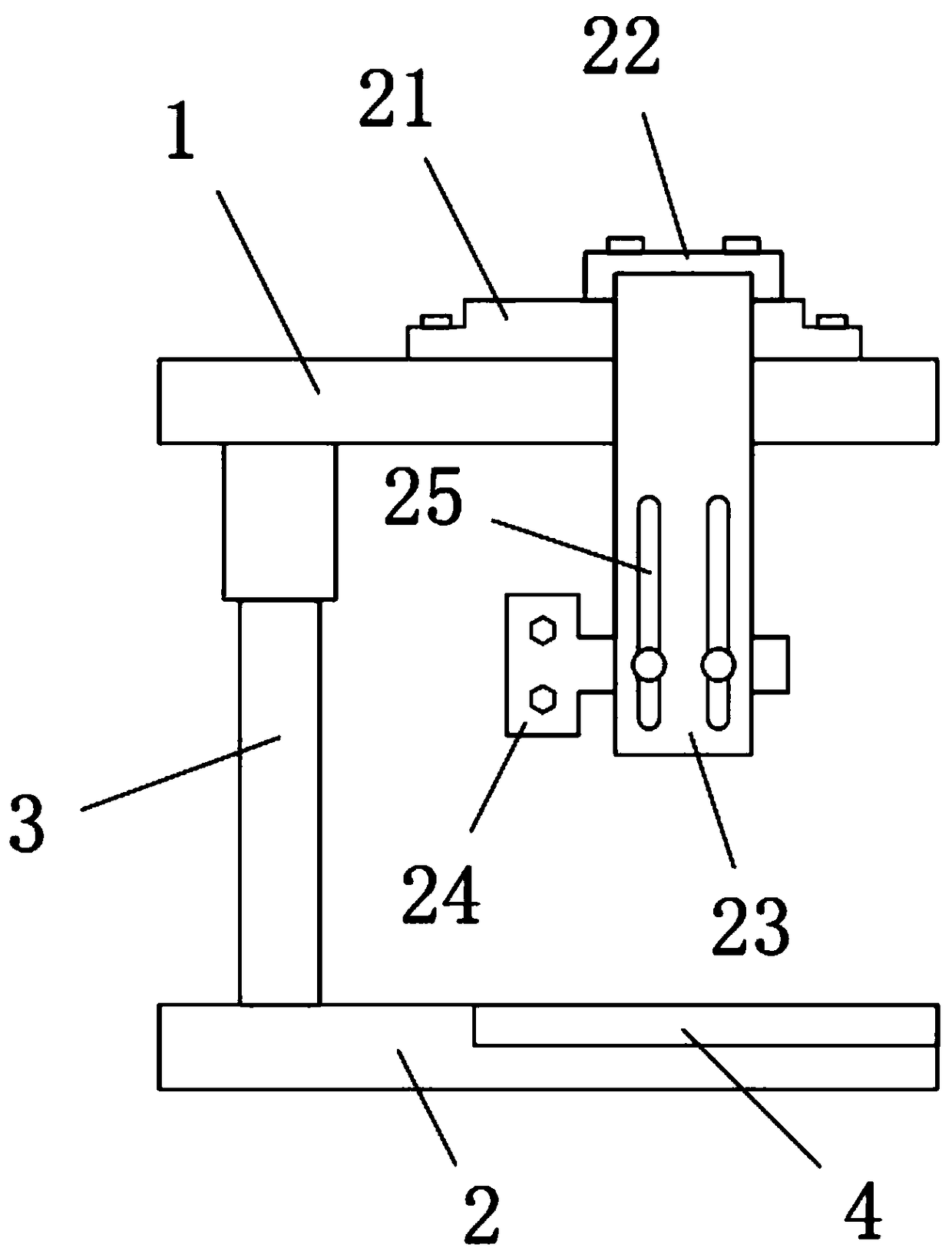
[0012] as attached figure 1 As shown, a unilateral guide column formwork according to the present invention includes an upper fixed plate 1, a lower fixed plate 2, a guide post 3 and a side locking assembly; the upper fixed plate 1 and the lower fixed plate 2 are arranged horizontally , and connected by guide post 3, there are two guide posts 3, the two guide posts 3 are located on the rear side of the upper fixed plate 1 and the lower fixed plate 2, and are respectively arranged on the rear sides of the upper fixed plate 1 and the lower fixed plate 2 On the two corners; between the upper fixing plate 1 and the lower fixing plate 2, there is a space for installing the mold core assembly, and the lower fixing plate 2 is provided with a positioning chute 4 that cooperates with the mold core assembly, and the positioning chute 4 Extending forward to the front end face of the lower fixing ...
PUM
 Abstract
Description
Claims
Application Information
 - Generate Ideas
- Intellectual Property
- Life Sciences
- Materials
- Tech Scout
- Unparalleled Data Quality
- Higher Quality Content
- 60% Fewer Hallucinations
Browse by: Latest US Patents, China's latest patents, Technical Efficacy Thesaurus, Application Domain, Technology Topic, Popular Technical Reports.
© 2025 PatSnap. All rights reserved.Legal|Privacy policy|Modern Slavery Act Transparency Statement|Sitemap|About US| Contact US: help@patsnap.com