Double-tension thread clamp

A thread tensioner and tension technology, applied in the direction of tension devices, sewing equipment, sewing machine components, etc., can solve the problems of inconsistent suture tension, difficulty in fine-tuning, easy thread breakage, etc., to ensure accuracy and save space , the effect of improving efficiency

Inactive Publication Date: 2018-10-26
SUZHOU KAICHENG SEWING EQUIP
View PDF0 Cites 2 Cited by
  • Summary
  • Abstract
  • Description
  • Claims
  • Application Information

AI Technical Summary

Problems solved by technology

[0002] The current sewing machine is equipped with a thread clamp. When sewing, the thread clamp needs to clamp the suture and give the suture an appropriate clamping force: if the clamping force is too large, the needle guides the suture when sewing. If the tension on the suture is too large, the thread will be easily broken; if the clamping force is too small, the tension on the suture will be too small when the needle guides the suture to sew, which will affect the quality of the stitches. Most of the thread tensioners use two thread tension nuts to adjust the tension of the two sutures respectively. However, this thread tensioner has the following defects: First, each suture is only adjusted with one thread tension nut, which is difficult to achieve fine adjustment. It is very easy to cause the tension of the two groups of sutures to be inconsistent, which seriously affects the sewing quality; secondly, the two groups of loosening nails cannot be lifted up at the same time when the loosening plate is lifting the thread, and the opening and closing amount of the clamping plate cannot meet the requirements, making the clamping thread The tightness of the pressure plate is inconsistent, resulting in unsightly sewing stitches and unable to meet market demand

Method used


Image

  • Double-tension thread clamp
  • Double-tension thread clamp
  • Double-tension thread clamp

Examples


Embodiment Construction

[0017] The preferred embodiments of the present invention will be described below in conjunction with the accompanying drawings. It should be understood that the preferred embodiments described here are only used to illustrate and explain the present invention, and are not intended to limit the present invention.

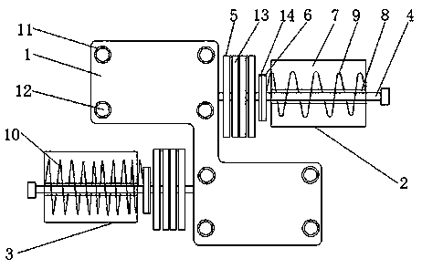
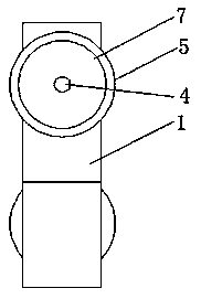
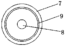
[0018] Such as Figure 1-3 As shown, a double tension tensioner includes a mounting base 1 for installation, and the two sides of the mounting base 1 are respectively fixedly connected with a coarse adjustment tensioner 2 and a fine adjustment tensioner 3, both of which are used to adjust tension of the upper thread, and the coarse thread tension device 2 is located above the fine thread tension device 3, the coarse thread tension device 2 and the fine thread tension device 3 both include a screw rod 4, a thread tension assembly 5, a push plate 6 and connecting block 7, the screw 4 is used to connect the clamping assembly 5, the push plate 6 and the connecting block...


PUM


Abstract

The invention relates to a double-tension thread clamp. The double-tension thread clamp is characterized in that a rough adjusting thread clamp and a fine adjustment thread clamp are fixedly connectedwith two sides of a mounting seat, the rough adjustment thread clamp is positioned above the fine adjustment thread clamp, the rough adjustment thread clamp and the fine adjustment thread clamp comprise screws, thread clamping assemblies, push plates and connecting blocks, one end of each screw is fixedly connected with the mounting seat, the screws penetrate the thread clamping assemblies, the push plates and the connecting blocks and are movably connected with the thread clamping assemblies, each thread clamping assembly is positioned on a side of the corresponding push plate and is movablyconnected with the push plate, each push plate is positioned on a side of the corresponding connecting block and is movably connected with the connecting block, threaded pipes are fixedly connected into the connecting blocks, a first spring is arranged on the rough adjustment thread clamp, and a second spring is arranged on the fine adjustment thread clamp. The double-tension thread clamp has theadvantages that the double-tension thread clamp is simple and reasonable in structure, the upper thread adjustment accuracy can be effectively improved, and the work efficiency and the product quality can be improved.

Description

technical field [0001] The invention relates to a double-tension thread gripper, which belongs to the technical field of thread grippers. Background technique [0002] The current sewing machine is equipped with a thread clamp. When sewing, the thread clamp needs to clamp the suture and give the suture an appropriate clamping force: if the clamping force is too large, the needle guides the suture when sewing. If the tension on the suture is too large, the thread will be easily broken; if the clamping force is too small, the tension on the suture will be too small when the needle guides the suture to sew, which will affect the quality of the stitches. Most of the thread tensioners use two thread tension nuts to adjust the tension of the two sutures respectively. However, this thread tensioner has the following defects: First, each suture is only adjusted with one thread tension nut, which is difficult to achieve fine adjustment. It is very easy to cause the tension of the tw...

Claims


Application Information

Patent Timeline
Patent Type & Authority Applications(China)
IPC IPC(8): D05B47/04
CPCD05B47/04
Inventor 季锴
Owner SUZHOU KAICHENG SEWING EQUIP
Why Eureka
Try Eureka