Laundry rack

A technology of clothes drying rack and clothes drying rod, applied in the field of clothes drying rack, can solve the problems of inconvenient operation, waste of electric energy, poor power supply effect, etc., and achieve the effects of saving space, improving comfort, and improving utilization rate of light energy.

Pending Publication Date: 2018-10-26
SHENZHEN ORLANT INTELLIGENT CONTROL SYST CO LTD
View PDF0 Cites 0 Cited by
  • Summary
  • Abstract
  • Description
  • Claims
  • Application Information

AI Technical Summary

Problems solved by technology

There are two ways to control the up and down of the clothes drying pole. One is mechanical lifting, which needs to be done manually, which is not easy to operate; the other is electric lifting, which requires an external power supply or a built-i

Method used


Image

  • Laundry rack
  • Laundry rack
  • Laundry rack

Examples


Embodiment Construction

[0028] The following will clearly and completely describe the technical solutions in the embodiments of the present invention with reference to the accompanying drawings in the embodiments of the present invention. Obviously, the described embodiments are only part of the embodiments of the present invention, not all of them. Based on the embodiments of the present invention, all other embodiments obtained by persons of ordinary skill in the art without creative efforts fall within the protection scope of the present invention.

[0029] It should be noted that all directional indications (such as up, down, left, right, front, back...) in the embodiments of the present invention are only used to explain the relationship between the components in a certain posture (as shown in the accompanying drawings). Relative positional relationship, movement conditions, etc., if the specific posture changes, the directional indication will also change accordingly.

[0030] In the present in...


PUM


Abstract

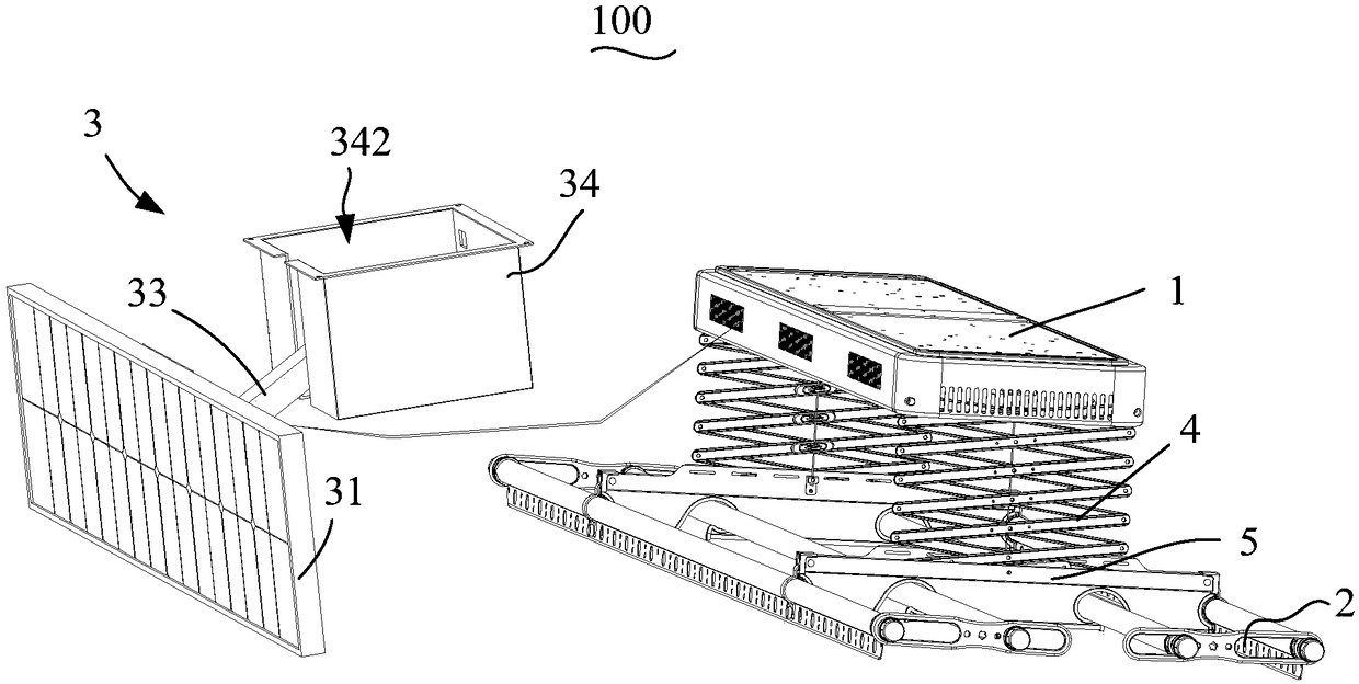
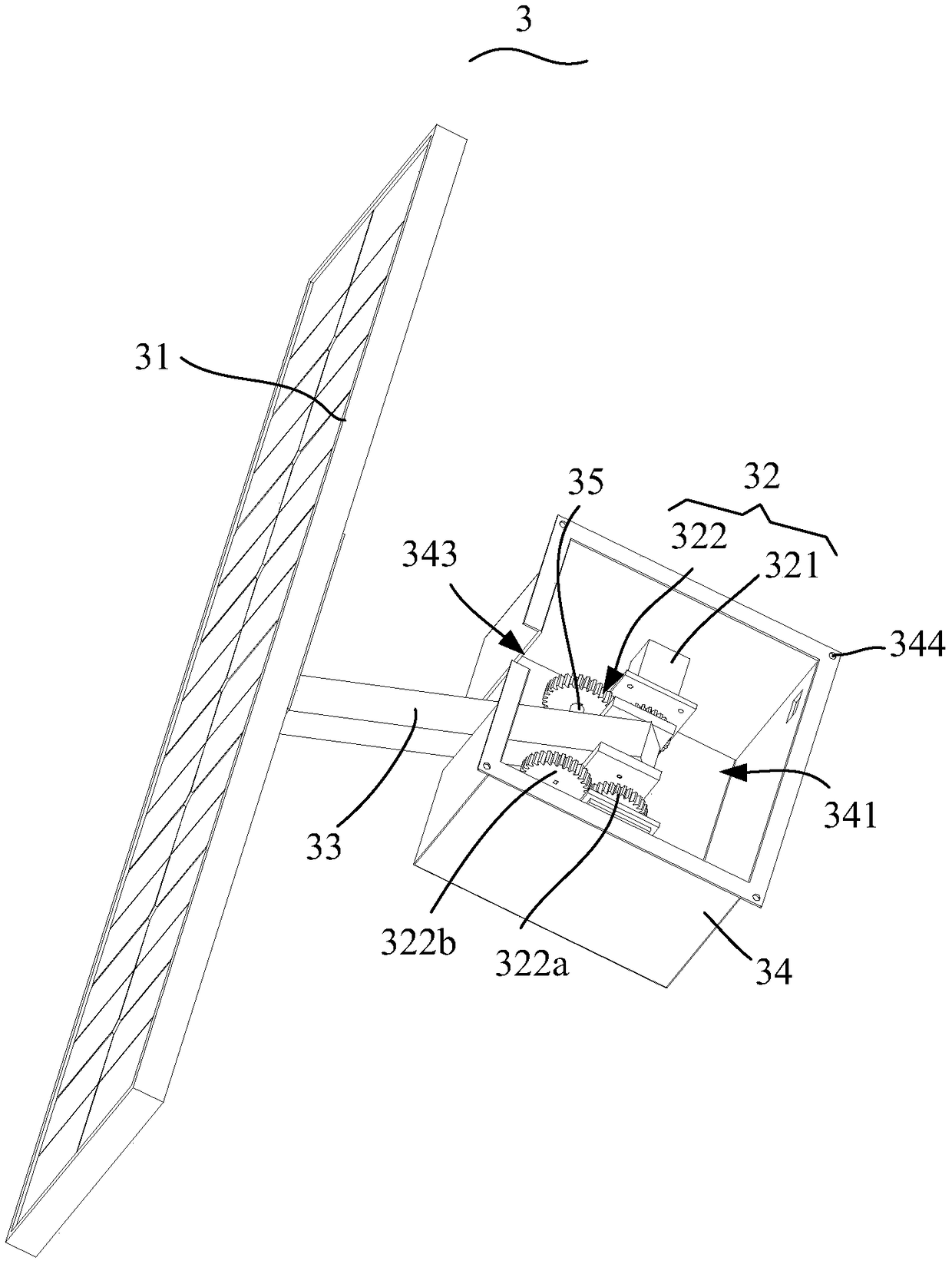
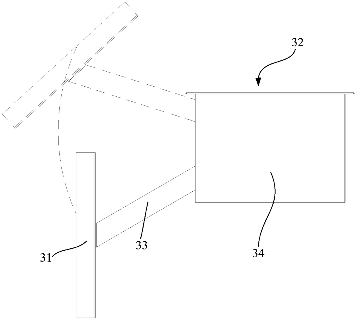
The invention discloses a laundry rack. The laundry rack comprises a base, laundry poles and a solar panel component. The base comprises a mounting shell fixed to a ceiling, and a first driving part is electrically connected with a battery component mounted in the mounting shell. The laundry poles are arranged under the base, mechanically connected with the first driving part and driven to move upand down by the first driving part. The solar panel component comprises a solar panel and a second driving part, the solar panel is in electrical connection with the battery component, and the seconddriving part is in rotational connection with the solar panel and drives the solar panel to rotate to adjust an angle between the solar panel and the sunlight. By adoption of the technical scheme, the laundry rack has the advantage of improvement of power supply effects.

Description

technical field [0001] The invention relates to the technical field of home improvement, in particular to a clothes drying rack. Background technique [0002] In order to dry clothes, people generally set clothes racks on the balcony of the living room. The clothes racks are divided into two structures: fixed and lifting. Because the latter is convenient for drying clothes and saving space, it is widely used. There are two ways to control the up and down of the clothes drying pole. One is mechanical lifting, which needs to be done manually, which is not easy to operate; the other is electric lifting, which requires an external power supply or a built-in battery, which wastes electric energy. In order to solve the above problems at the same time, solar panels are arranged to provide power for the clothes hanger, but the structure of the current clothes hanger makes the power supply effect not good. Contents of the invention [0003] The main purpose of the present inventio...

Claims


Application Information

Patent Timeline
IPC IPC(8): D06F57/12D06F58/00D06F58/20
CPCD06F57/125D06F58/00D06F58/20Y02B40/18
Inventor 王大安梁春孟
Owner SHENZHEN ORLANT INTELLIGENT CONTROL SYST CO LTD
Why Eureka
Try Eureka