
A detachable intelligent temperature-controlled drying rack

A technology of intelligent temperature control and drying rack, applied in washing devices, household dryers, textiles and papermaking, etc., can solve the problems of inability to adjust height, space expansion, disassembly and assembly, easy touch, burns, etc., to avoid The effect of frequent contact with the control switch parts, reducing burns and improving usability

Active Publication Date: 2019-09-13
JIANGXI AVONFLOW HVAC TECH CO LTD
View PDF8 Cites 0 Cited by
  • Summary
  • Abstract
  • Description
  • Claims
  • Application Information

AI Technical Summary

Problems solved by technology

As a supporting product for bathroom products, the drying rack has been popularized to thousands of households. Most of the existing drying rack products on the market are fixed by welding at the connection position. Once the drying rack leaks air and water, it cannot be used, and maintenance is troublesome. And it is not possible to flexibly adjust the height, space expansion and disassembly and assembly according to the different use spaces and usage conditions of the user, which brings inconvenience to the user. In addition, the switch control of the drying rack is generally installed on one side of the drying rack. During the switching process, because it is too close to the drying rack, it is easy to touch and cause burns

Method used


Image

  • A detachable intelligent temperature-controlled drying rack
  • A detachable intelligent temperature-controlled drying rack
  • A detachable intelligent temperature-controlled drying rack

Examples


Embodiment Construction

[0026] The following will clearly and completely describe the technical solutions in the embodiments of the present invention with reference to the accompanying drawings in the embodiments of the present invention. Obviously, the described embodiments are only some, not all, embodiments of the present invention. The specific embodiments described here are only used to explain the present invention, not to limit the present invention. Based on the embodiments of the present invention, all other embodiments obtained by persons of ordinary skill in the art without making creative efforts belong to the protection scope of the present invention.

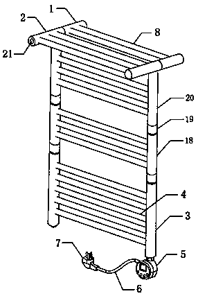
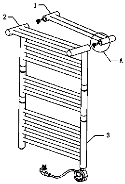
[0027] Such as Figure 1-5 As shown, a detachable intelligent temperature-controlled drying rack includes a fixed pipe 1 , an installation pipe 2 , a first vertical pipe 3 , a second vertical pipe 20 and at least one intermediate vertical pipe 18 .

[0028] The first vertical pipe 3 is located at the lowermost end of the drying rack, and...


PUM


Abstract

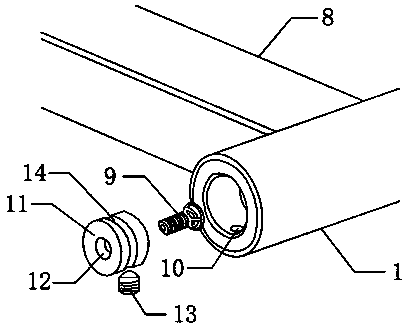
The invention discloses a removable intelligent temperature control type drying frame which comprises a fixed tube, a mounting tube, a first vertical tube, a second vertical tube and at least one middle vertical tube. An electric heating tube is mounted inside the first vertical tube, a temperature controller is mounted at the bottom of the first vertical tube, and an infrared induction switch isfixedly mounted on the lower portion of the temperature controller. The middle vertical tubes are mounted at the upper end of the first vertical tube through threaded sleeves, the second vertical tubeis mounted at the upper ends of the middle vertical tubes through threaded sleeves, the threaded sleeves are used for detachably mounting the middle vertical tubes with different lengths or heights or mounting the middle vertical tubes in a freely combined manner, the upper end of the second vertical tube is communicated with the mounting tube, and a fixed block is mounted at one end of the mounting tube through a bolt, inserted into one end of the fixed tube and fixed by a glass bead screw. The drying frame can be freely removed and extended and is strong in practicability, non-contact control can be performed, and scalding is decreased.

Description

technical field [0001] The invention belongs to the technical field of smart home equipment, and in particular relates to a detachable smart temperature-controlled drying rack. Background technique [0002] With the rapid development of social economy, the intelligence of household equipment has become an inevitable demand for the development of the times. As a supporting product for bathroom products, the drying rack has been popularized to thousands of households. Most of the existing drying rack products on the market are fixed by welding at the connection position. Once the drying rack leaks air and water, it cannot be used, and maintenance is troublesome. And it is not possible to flexibly adjust the height, space expansion and disassembly and assembly according to the different use spaces and usage conditions of the user, which brings inconvenience to the user. In addition, the switch control of the drying rack is generally installed on one side of the drying rack. Du...

Claims


Application Information

Patent Timeline
Patent Type & Authority Patents(China)
IPC IPC(8): D06F58/00D06F58/20D06F58/26A47K10/06
Inventor 吴剑斌张卫王春迎
Owner JIANGXI AVONFLOW HVAC TECH CO LTD
Learn More