Touch control panel and touch control display device using touch control panel

A touch panel and substrate technology, applied in the input/output process of data processing, instruments, electrical digital data processing, etc., can solve the problem that touch panels cannot meet user needs, uneven sensitivity, single sensitivity of touch panels, etc. question

Active Publication Date: 2018-10-26
INTERFACE TECH CHENGDU CO LTD +2
View PDF8 Cites 3 Cited by
  • Summary
  • Abstract
  • Description
  • Claims
  • Application Information

AI Technical Summary

Problems solved by technology

[0003] However, the existing touch panels generally only have a single sensitivity. As users tend to have more and more diversified demands on the performance and appearance of electronic products, whether it is a flat electronic product or a curved electronic product, only a single sensitivity is required. The sensitivity of the touch panel can not meet the needs of users
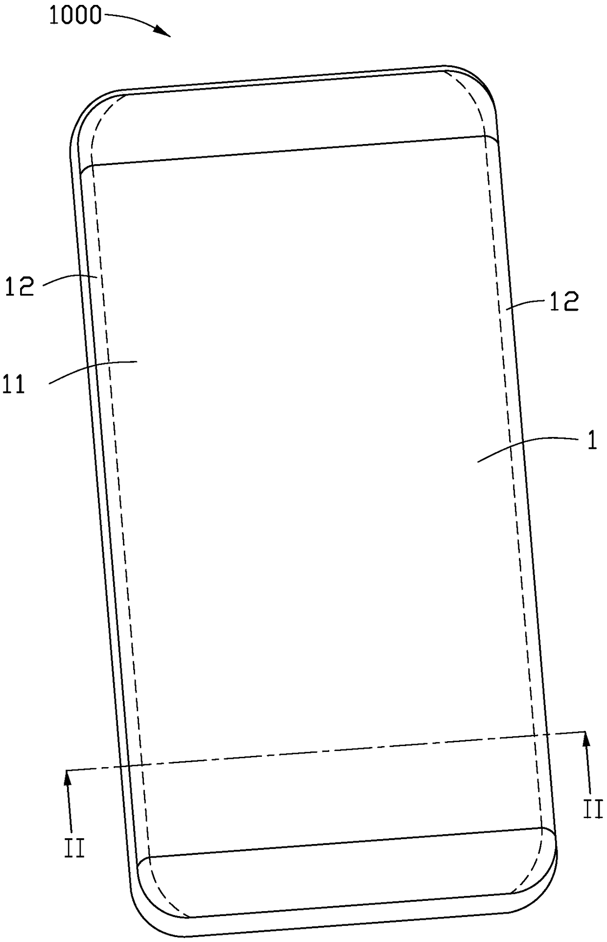
[0004] Take an electronic product with a curved surface as an example. In order to prevent the cover from breaking due to stress in the curved part of the curved electronic product, the cover at the curved part is usually designed to be thicker. However, because the cover is thicker at the curved part and The existing touch panel has the same sensitivity in each area, and the touch sensing sensitivity is affected by the distance between the touch position and the touch panel, and the larger thickness of the bend of the cover causes the difference in the distance. increase, so the touch sensing sensitivity of the electronic product at the bend will be smaller than that at the plane, resulting in uneven sensitivity in different areas of the electronic product, affecting product performance

Method used


Image

  • Touch control panel and touch control display device using touch control panel
  • Touch control panel and touch control display device using touch control panel
  • Touch control panel and touch control display device using touch control panel

Examples


Embodiment Construction

[0049] The drawings illustrate embodiments of the invention, which may be embodied in many different forms and should not be construed as limited to only the embodiments set forth herein. Rather, these embodiments are provided so that the disclosure of the present invention will be more thorough and complete, and the scope of the present invention will be fully understood by those skilled in the art. In the drawings, the dimensions of layers and regions are exaggerated for clarity.

[0050] It will be understood that although the terms first, second, etc. may be used herein to describe various elements, components, regions, layers and / or sections, these elements, components, regions, layers and / or sections should not be limited to these the term. These terms are only used to distinguish an element, component, region, layer and / or section from another element, component, region, layer and / or section. Thus, a first element, component, region, layer and / or section discussed bel...


PUM


Abstract

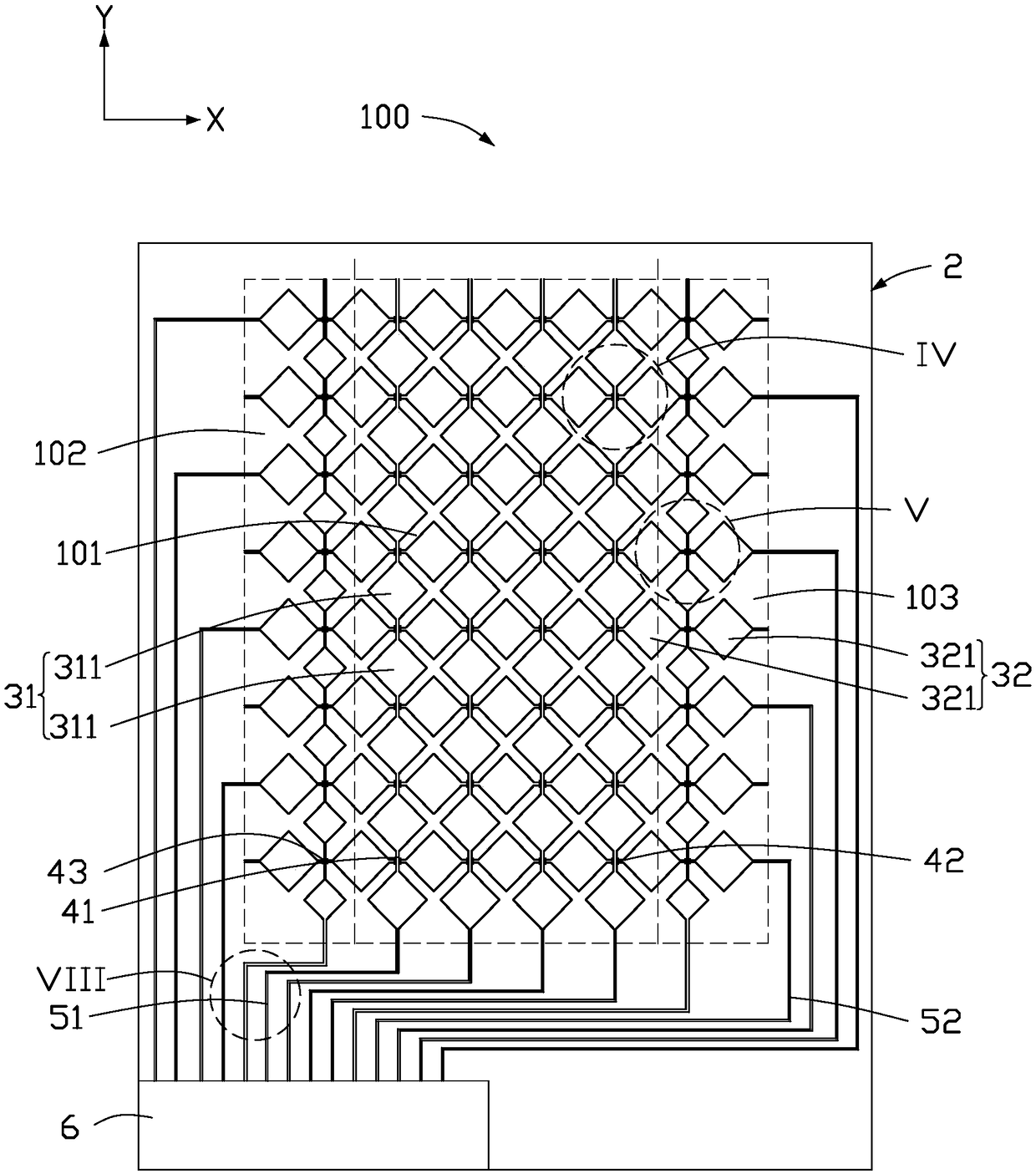
The invention provides a touch control panel. The touch control panel comprises a substrate, and a plurality of first sensing electrodes and a plurality of second sensing electrodes, wherein the plurality of first sensing electrodes and the plurality of second sensing electrodes are formed on the substrate; the two adjacent first sensing circuits are connected with each other through a first bridging part; the two adjacent second sensing circuits are connected with each other through a second bridging part; a distance between the corresponding first sensing electrode and the corresponding second sensing circuit adjacent to each other is defined as a space; the size of at least one space is different from the size of the other spaces or the superposition area between the first bridging partand the second bridging part is different or a distance between the first bridging part and the second bridging part corresponding to the first bridging part is different. The sensing electrodes of the touch control panel disclosed by the invention have different spaces or the bridging parts have different superposition areas or the bridging parts have different distances, so that different sensing sensitivity is formed in the touch control panel.

Description

technical field [0001] The invention relates to a touch panel and a touch display device using the touch panel. Background technique [0002] In today's market of various consumer electronic products, portable electronic products such as personal digital assistants (PDAs), mobile phones (mobilePhone), notebook computers (notebooks) and tablet computers (tablet PCs) have been widely used. The control panel (touch pane1) is used as the interface tool for data input. Wherein, the capacitive type touch panel can confirm the touch position by using the capacitance change induced between the static electricity of the human body and the electrode for inducing current. To detect where a finger or stylus touches a touch panel, various capacitive touch technologies have been developed. [0003] However, the existing touch panels generally only have a single sensitivity. As users tend to have more and more diversified demands on the performance and appearance of electronic products, ...

Claims


Application Information

Patent Timeline
Patent Type & Authority Applications(China)
IPC IPC(8): G06F3/044G06F3/041
CPCG06F3/0412G06F3/044
Inventor 陈彦勋李璟林
Owner INTERFACE TECH CHENGDU CO LTD
Why Eureka
Try Eureka