Electric connector

An electrical connector and electrical connection technology, which is applied in the direction of conductive connection, connection, welding/welding connection, etc., can solve the problem of increasing terminal impedance, the gap between the contact and the main elastic arm, and the left and right deflection of the main elastic arm of the contact, etc. problem, to achieve the effect of reducing contact impedance, good stabilization effect, and conducive to transmission

Active Publication Date: 2018-10-26
DEYI PRECISION ELECTRONIC IND CO LTD PANYU
View PDF5 Cites 4 Cited by
  • Summary
  • Abstract
  • Description
  • Claims
  • Application Information

AI Technical Summary

Problems solved by technology

[0003] However, the contact is the elastic end of the auxiliary elastic arm, which can slide freely along the main elastic arm, and both the main elastic arm and the auxiliary elastic arm are located on the upper surface of the insulating body. The arm and the auxiliary elastic arm are easily affected by external force, so that the auxiliary elastic arm is easily deformed and the contact is deflected left and right relative to the main elastic arm, resulting in a gap between the contact and the main elastic arm, resulting in the auxiliary elastic arm and the main elastic arm. The main elastic arms are separated, so that when the main elastic arm is pressed down, the auxiliary elastic arm

Method used


Image

  • Electric connector
  • Electric connector
  • Electric connector

Examples


Example Embodiment

[0040] In order to facilitate a better understanding of the purpose, structure, features and effects of the present invention, the present invention will now be further described with reference to the accompanying drawings and specific embodiments.

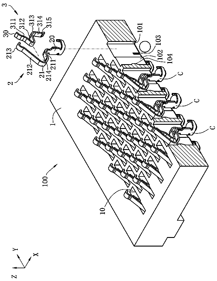
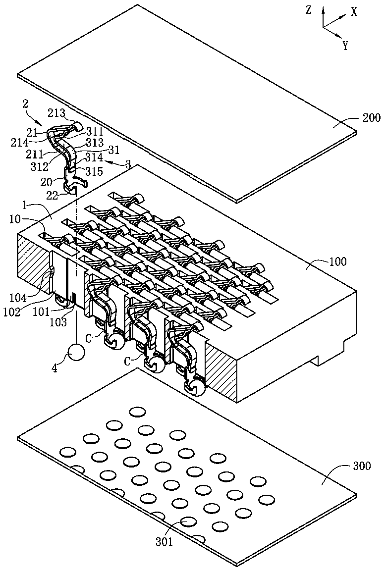
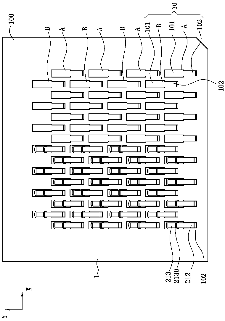
[0041] see figure 1 , figure 2 and image 3 , which is an embodiment of an electrical connector 100 of the present invention. The electrical connector 100 is mounted on a circuit board 300 along a vertical direction Z, the circuit board 300 has a plurality of pads 301 , and the electrical connector 100 is connected to a chip module 200 along the vertical direction Z , the chip module 200 is provided with a plurality of conductive sheets 201 . The electrical connector 100 has an insulating body 1 , a plurality of terminals C are accommodated in the insulating body 1 , the upper end of each of the terminals C electrically contacts the conductive sheet 201 , and the lower end of each of the terminals C is matched with a Tin mate...


PUM


Abstract

The invention discloses an electric connector. The electric connector is used for electrically connected with an electronic element and a circuit board, and is characterized in that the electric connector comprises an insulation body, at least one first terminal and at least one second terminal. Each first terminal comprises a base part accommodated in the insulation body, and a first elastic armwhich upwards extends from the base part and is at least partially arranged on the insulation body and used for being in abutted contact with the electronic element. Each second terminal comprises a fixed end and second elastic arm, wherein the fixed end is connected with the second elastic arm. Each fixed end is at least partially arranged on the insulation body and welded to the corresponding first elastic arm. Each second elastic arm is in sliding contact with the corresponding first terminal.

Description

technical field [0001] The invention relates to an electrical connector, in particular to an electrical connector for connecting a chip module to a circuit board with a terminal of double conduction channels. Background technique [0002] A conventional electrical connector has an insulating body, a plurality of terminals are accommodated in the insulating body, each terminal has a base part accommodated in the insulating body, and the upper end of the base extends upwards out of a main spring arm above the insulating body , the upper end of the main elastic arm has a contact portion for abutting contact with a chip module, the lower end of the base portion extends upwards from an auxiliary elastic arm on the upper surface of the insulating body, and the free end of the auxiliary elastic arm has a contact, upward When the chip module abuts against the main elastic arm, the main elastic arm moves downward, and the auxiliary elastic arm slides along the main elastic arm and su...

Claims


Application Information

Patent Timeline
IPC IPC(8): H01R12/71H01R13/24H01R13/46H01R33/74H01R4/02
CPCH01R4/029H01R12/716H01R13/2414H01R13/2442H01R13/46H01R33/74H01R12/707H01R12/714H01R12/73H01R13/2457H01R12/7076H01R13/41
Inventor 何建志金左锋
Owner DEYI PRECISION ELECTRONIC IND CO LTD PANYU
Why Eureka
Try Eureka