
Power metering cabinet

A technology of power metering cabinet and metering cabinet, applied in the field of metering cabinet, can solve the problems of troublesome beam operation and inconvenient beam fixing, etc., and achieve the effect of rational utilization

Active Publication Date: 2018-10-26
PENGLAI POWER SUPPLY CO OF STATE GRID SHANDONG ELECTRIC POWER CO
View PDF7 Cites 8 Cited by
  • Summary
  • Abstract
  • Description
  • Claims
  • Application Information

AI Technical Summary

Problems solved by technology

[0002] The power metering cabinet is an electric energy metering device, and current transformers, junction boxes, and electric energy meters are installed in the power metering cabinet. Power metering cabinet, this structure is equipped with a lock door assembly between the cabinet door and the cabinet body of the power metering cabinet, and the door is locked by the lock door assembly, and a beam is arranged in the cabinet body, and the beam is adjustable up and down It is installed in the cabinet to facilitate the installation of the device. Since the types of various devices that need to be installed in the power metering cabinet are different, the requirements for the position of the beam are also different, but the above structure is more troublesome for the operation of the height adjustment of the beam. It is not convenient to fix the position of the beam, so we propose a power metering cabinet to solve the above problems

Method used


Image

  • Power metering cabinet
  • Power metering cabinet
  • Power metering cabinet

Examples


Embodiment

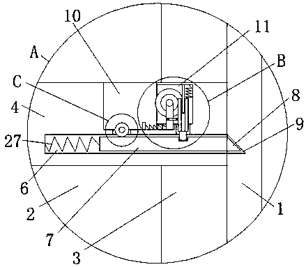
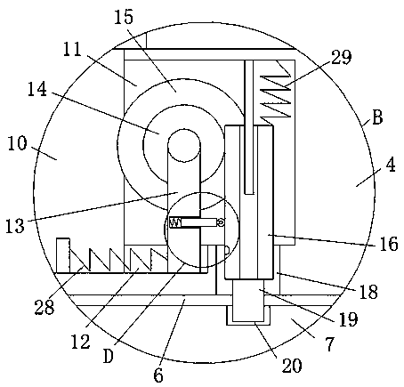
[0026] refer to Figure 1-5 In this embodiment, a power metering cabinet is proposed, including a metering cabinet body 1, a working chamber 2 is provided on the metering cabinet body 1, and chutes 3 are provided on the inner walls of both sides of the working chamber 2, and sliding in the two chutes 3 A plurality of bearing plates 4 are installed, and positioning grooves 5 are provided at the central positions of the bottoms of the plurality of bearing plates 4, and both sides of the bearing plate 4 are provided with post slots 6, and post slots 7 are slidably installed in the post slots 6. The side of the card column 7 away from the positioning groove 5 is welded with a triangular block 8, and the inner wall of the side where the two chutes 3 are far away from each other is provided with a plurality of triangular card slots 9 that are compatible with the triangular block 8, and the triangular card The block 8 is engaged with the corresponding triangular card slot 9, and both...


PUM


Abstract

The invention discloses a power metering cabinet, which comprises a metering cabinet body, wherein a working chamber is formed in the metering cabinet body; sliding chutes are formed in inner walls attwo sides of the working chamber; a plurality of bearing plates are arranged in each of two sliding chutes in a sliding manner; positioning grooves are formed in the bottom center positions of the plurality of bearing plates; clamping column grooves are formed in two sides of each bearing plate; a clamping column is arranged in each clamping column groove in a sliding manner; a triangular clamping block is connected with one side, far away from the corresponding positioning groove, of each clamping column in a welding manner; a plurality of triangular clamping grooves matched with the triangular clamping blocks are formed in each of the inner walls at one sides, which are far away from each other, of the two sliding chutes; and the triangular clamping blocks are clamped in the corresponding triangular clamping grooves. The power metering cabinet is high in practical performance, simple in structure and convenient to operate, and adjustment of the heights of the plurality of bearing plates is facilitated, thereby conveniently arranging instruments and equipment of different heights in the metering cabinet body on the bearing plates, reasonably utilizing the space in the metering cabinet body and being convenient for people to use.

Description

technical field [0001] The invention relates to the technical field of metering cabinets, in particular to an electric power metering cabinet. Background technique [0002] The power metering cabinet is an electric energy metering device, and current transformers, junction boxes, and electric energy meters are installed in the power metering cabinet. Power metering cabinet, this structure is equipped with a lock door assembly between the cabinet door and the cabinet body of the power metering cabinet, and the door is locked by the lock door assembly, and a beam is arranged in the cabinet body, and the beam is adjustable up and down It is installed in the cabinet to facilitate the installation of the device. Since the types of various devices that need to be installed in the power metering cabinet are different, the requirements for the position of the beam are also different, but the above structure is more troublesome for the operation of the height adjustment of the beam. ...

Claims


Application Information

Patent Timeline
Patent Type & Authority Applications(China)
IPC IPC(8): H02B1/34H02B1/03H02B1/04
CPCH02B1/03H02B1/04H02B1/34
Inventor 杨砚澜徐蔚业孙凌云丛安堂赵梅赵红霞孙作军宋宇张莉孙兵高录于晶倩于波刘军宋士伟葛树尊于大明聂晶宫恩臣王莹姜洪毅牟逵
Owner PENGLAI POWER SUPPLY CO OF STATE GRID SHANDONG ELECTRIC POWER CO
Learn More