Suction nozzle for a vacuum cleaning device

A technology for cleaning equipment and processing equipment, which is applied in the field of functional parts to achieve the effect of reducing power consumption

Inactive Publication Date: 2018-11-02
VORWERK & CO INTERHOLDING GMBH
View PDF1 Cites 1 Cited by
  • Summary
  • Abstract
  • Description
  • Claims
  • Application Information

AI Technical Summary

Problems solved by technology

This requires a correspondingly strong lifting element, which in turn requires a larger installation space for the suction nozzle

Method used


Image

  • Suction nozzle for a vacuum cleaning device
  • Suction nozzle for a vacuum cleaning device
  • Suction nozzle for a vacuum cleaning device

Examples


Embodiment Construction

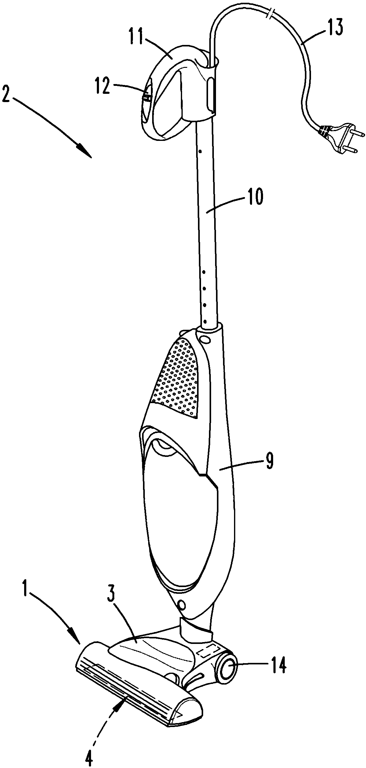
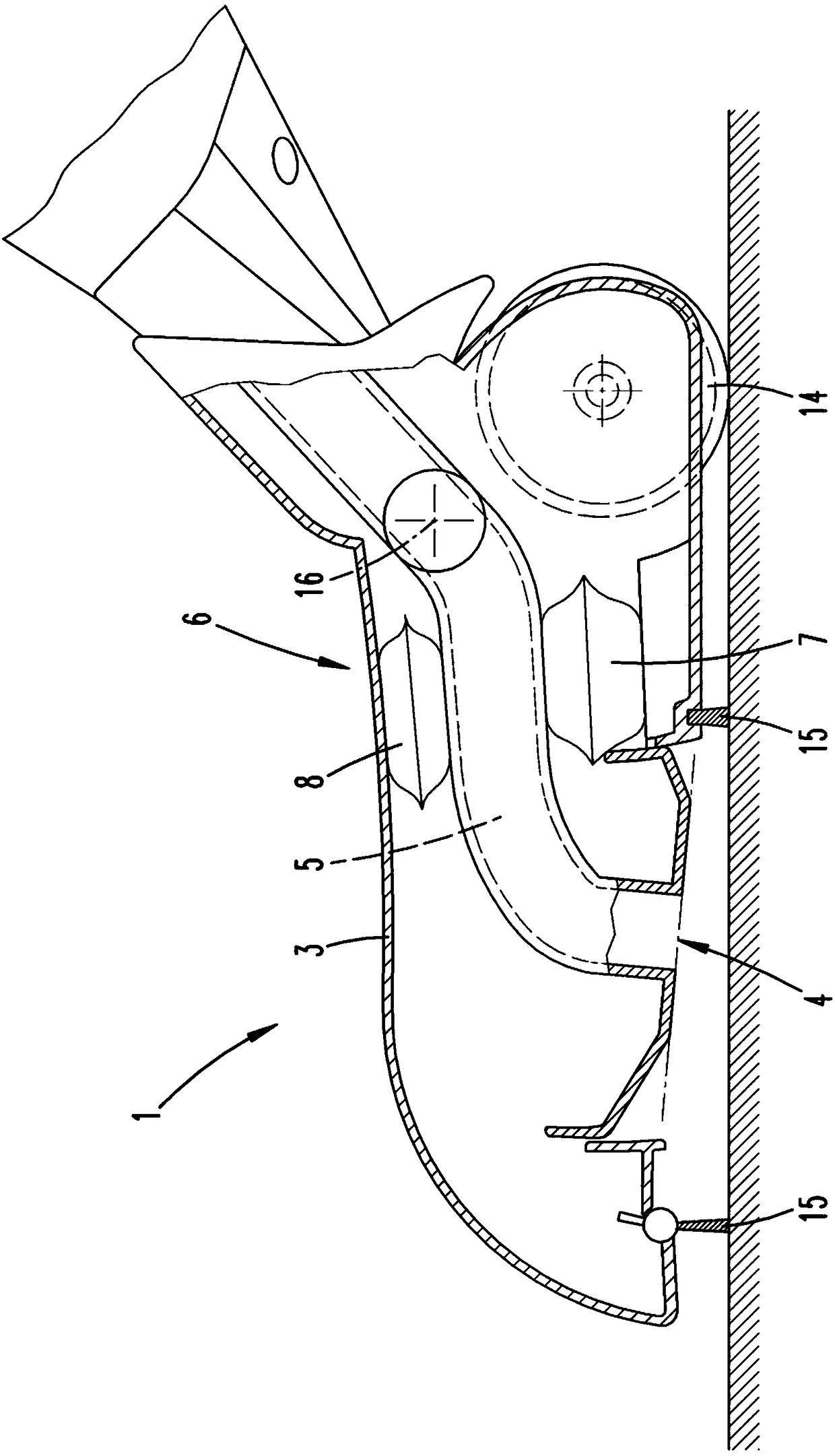
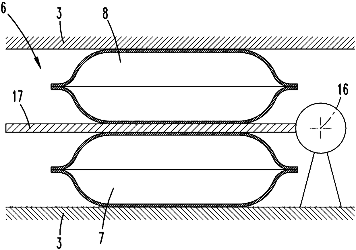
[0030] figure 1 A dust extraction device 2 with a suction nozzle 1 is shown by way of example. The vacuum cleaner 2 is designed here as a hand-held vacuum cleaner. The suction nozzle 1 is here a separate accessory device which can be detached from the base device 9 of the dust suction device 2 . In a general manner, the dust extraction device 2 has a motor-driven fan (not shown), by means of which suction material can be collected from the surface to be cleaned. For this purpose, the fan creates a suction air flow which flows through the suction channel 5 of the suction nozzle 1 . The suction channel 5 opens into the suction opening 4 on the underside. Furthermore, the suction nozzle 1 has a housing 3 on which two rollers 14 are mounted, which roll on the surface to be cleaned when the suction nozzle 1 is moved.

[0031] The base device 9 is connected to a pole 10 which can be configured telescopically in order to adjust the length of the pole 10 to the height of the user....


PUM


Abstract

The invention relates to a functional part of a cultivator, in particular a suction nozzle (1), with an actuator (6) from a first to a second position, and vice versa, displaceable component. In orderto shift the functional part from a hard floor position into a carpet position, or vice versa, the actuator (6) has two mechanically coupled expansion elements (7, 8) which can be acted upon by air pressure whose expansion directions are opposite to one another.

Description

technical field [0001] The invention relates to a functional part of a ground handling device having a component that can be moved by means of an actuator from a first position to a second position and vice versa from the second position to the first position. [0002] Furthermore, the invention relates to a ground treatment device with a functional part. [0003] Furthermore, the invention relates to a method for operating a floor treatment installation with a function, wherein a component of the function is moved by means of an actuator from a first position to a second position and vice versa from the second position to the third position. a location. Background technique [0004] Functions of the above-mentioned type, such as suction nozzles, are known. The functional part can either be arranged on the basic device in the manner of an accessory device, or it can be an inseparable part of the ground handling device. Furthermore, the floor treatment device can also be, ...

Claims


Application Information

Patent Timeline
Patent Type & Authority Applications(China)
IPC IPC(8): A47L9/02
CPCA47L9/02A47L5/34A47L9/0494A47L9/0646
Inventor J.穆德拉克M.塞尔奈奇C.斯特尔
Owner VORWERK & CO INTERHOLDING GMBH
Why Eureka
Try Eureka