Clamping device for cuboid workpiece

A clamping device and cuboid technology, which is applied in positioning devices, metal processing machinery parts, clamping, etc., can solve the problems of excessive clamping range and unfavorable workpiece processing, etc., and achieve the effect of reducing the clamping range

Inactive Publication Date: 2018-11-02
王翔
View PDF0 Cites 3 Cited by
  • Summary
  • Abstract
  • Description
  • Claims
  • Application Information

AI Technical Summary

Problems solved by technology

[0003] The purpose of the present invention is to provide a clamping device for cuboid workpieces in view of the above problems, which is specially suitable for clamping cuboid workpieces, and solves the technical problem that the clamping range is too large to be unfavorable for the processing of workpieces

Method used


Image

  • Clamping device for cuboid workpiece

Examples


Embodiment Construction

[0022] All features disclosed in this specification, or steps in all methods or processes disclosed, may be combined in any manner, except for mutually exclusive features and / or steps.

[0023] Any feature disclosed in this specification (including any appended claims, abstract), unless otherwise stated, may be replaced by alternative features that are equivalent or serve a similar purpose. That is, unless expressly stated otherwise, each feature is one example only of a series of equivalent or similar features.

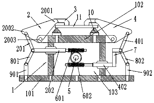
[0024] Such as figure 1 As shown, the clamping device for a rectangular parallelepiped workpiece includes a clamping device body 1, and the clamping device body 1 includes a support base 101, a compaction table 102 and a connecting cavity 103 between the support base 101 and the compaction table 102, The left end of the compacting table 102 is connected with the left compacting arm 2, and the right end of the compacting table 102 is connected with the right compacti...


PUM


Abstract

The invention discloses a clamping device for a cuboid workpiece. The clamping device comprises a clamping device body, wherein the clamping device body comprises a supporting base, a compacting platform and a connecting cavity formed between the supporting base and the compacting platform; the two ends of the compacting platform are connected with compacting arms respectively; the compacting armsare connected with force transmission arms respectively; the two force transmission arms are connected with a power device. The power device drives the two force transmission arms to move simultaneously so as to simultaneously and tightly clamp the cuboid workpiece through the compacting arms at the two ends of the compacting platform.

Description

technical field [0001] The invention relates to the technical field of clamping devices, in particular to a clamping device for cuboid workpieces. Background technique [0002] In the existing process of machining workpieces in mechanical manufacturing, it is often necessary to use clamping devices to clamp the workpieces before processing. However, the existing clamping device has the technical problems of complex structure and single function, and the clamping accuracy is not high, and even when the pressure of the clamping device is too large, it will cause certain damage to the workpiece. In addition, workpieces of different shapes require different In addition, some existing clamping devices need to have a large contact range with the workpiece to clamp the workpiece, which is not conducive to the processing of the workpiece due to the excessive clamping range. Contents of the invention [0003] The object of the present invention is to: aim at the above existing pro...

Claims


Application Information

Patent Timeline
Patent Type & Authority Applications(China)
IPC IPC(8): B23Q3/06
CPCB23Q3/06
Inventor 王翔
Owner 王翔
Why Eureka
Try Eureka