Simple cam press device

A technology of pressing device and cam, which is applied in the direction of positioning device, workpiece clamping device, clamping, etc., can solve the problems of small lift and unsuitable processing requirements, etc.

Inactive Publication Date: 2014-03-12
CHONGQING FENGGUO QIYANG TECH DEV
View PDF5 Cites 9 Cited by
  • Summary
  • Abstract
  • Description
  • Claims
  • Application Information

AI Technical Summary

Problems solved by technology

However, because the lift of the cam itself is small, if the cam is used to directly act on the workpiece to be processed, a large cam needs to be manufactured to meet the processing requir

Method used


Image

  • Simple cam press device

Examples


Embodiment Construction

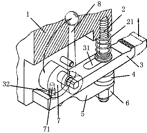
[0010] Such as figure 1 As shown, the simple cam pressing device of the present invention includes a fixed seat 1, on which there is a threaded hole, and a stud bolt 2 is connected in the threaded hole. The lower end of the stud bolt 2 is provided with a pressure plate 3, a spherical washer 4, a leaf spring 5 and a lock nut 6 in sequence, and a compression spring 21 is sleeved between the stud bolt 2 between the fixing seat 1 and the pressure plate 3. There is a bar hole 31 in the middle of the pressure plate 3 for the stud bolts to pass through. One end of the pressure plate 3 is a chuck for clamping the workpiece, and the other end is provided with a cam groove 32, and a cam 7 is placed in the cam groove 32. , a handle 8 is fixed on the cam 7. The rotating shaft of the handle 8 is fixed on the fixed seat 1; the bottom of the cam groove 31 is located between the cam 7 and the leaf spring 5 and a through hole is drilled, and the cam 7 is provided with a pressing plate ejector...


PUM


Abstract

The invention relates to a simple cam press device which comprises a fixing seat. A stud is connected to the fixing seat in a threaded mode, a press plate, a spherical washer, a plate spring and a locknut are arranged on the stud in sequence, a bar hole allowing the stud to penetrate through is formed in the middle of the press plate, a claming end is arranged at one end of the press plate, a cam groove is formed in the other end of the press plate, a cam is arranged in the cam groove, a handle is arranged on the cam, and a rotating shaft of the handle is fixedly arranged on the fixing seat. A through hole is formed in the bottom, between the cam and the plate spring, of the cam groove, and a press plate ejector pin inserted into the through hole is arranged on the cam. When the handle is rotated and is rotated in the claming direction, the handle drives the cam to move, the press plate ejector pin arranged on the cam drives the press plate to move horizontally at the moment, the handle is rotated continually when the press plate moves to the bar hole and butts against the stud, the whole press plate rotates with the stud as the rotating shaft under the squeezing of the cam at the moment, and thus pressing of a workpiece is achieved.

Description

technical field [0001] The invention relates to a fixture device in machining, in particular to a simple cam pressing device. Background technique [0002] Fixture is a common machining component, which has the function of clamping and positioning the workpiece to be processed. The cam is a common mechanical structure, and when the cam is used as a compression structure, it will not fail under greater pressure. It is an ideal clamping structure. However, because the lift of the cam itself is small, if the cam is used to directly act on the workpiece to be processed, a large cam needs to be manufactured to meet the processing requirements, which obviously does not meet the processing requirements, so it is necessary to design a cam that can rely on the action of the cam To realize the device for clamping the workpiece. Contents of the invention [0003] The object of the present invention is to provide a simple cam pressing device, which can realize the pressing of the w...

Claims


Application Information

Patent Timeline
IPC IPC(8): B25B11/00B23Q3/06
CPCB25B11/00
Inventor 姜静慧
Owner CHONGQING FENGGUO QIYANG TECH DEV
Why Eureka
Try Eureka