

Welding clamping method for automotive suspension control arm
A technology of automobile suspension and welding clip, which is applied in welding equipment, auxiliary welding equipment, welding/cutting auxiliary equipment, etc. Effect
- Summary
- Abstract
- Description
- Claims
- Application Information
AI Technical Summary
Problems solved by technology
Method used
Image

Examples
Embodiment
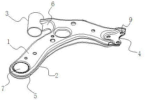
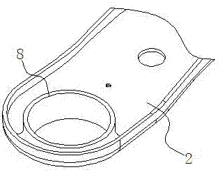
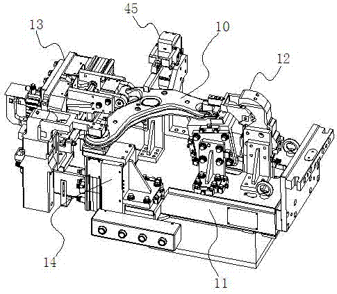
[0058] Example: such as image 3 and Figure 4 As shown, a welding and clamping method of an automobile suspension control arm 10, the welding method is to set a ball joint end clamping mechanism 12, a sleeve joint end clamping mechanism 13 and a ball stud on a working platform 11. End clamping mechanism 14, before welding, first utilize the ball joint end clamping mechanism 12 and the ball stud installation end clamping mechanism 14 to be positioned at the top cover 1 and the bottom at the ball joint end and the ball stud installation end. The cover 2 is clamped together, and then the sleeve 3 is pressed against the sleeve connection end by the clamping mechanism 13 of the sleeve connection end, and then welding is performed. In this embodiment, the clamping mechanism of the ball stud connecting end, the sleeve connecting end clamping mechanism and the ball stud mounting end clamping mechanism are set up to cooperate to perform clamping, so as to ensure the processing accura...
PUM
 Abstract
Description
Claims
Application Information