
Blow molding machine

A blow molding machine and frame technology, which is applied in the field of blow molding equipment, can solve the problems of easy cracking of mold clamping seams, increased labor costs, and reduced equipment costs, and achieves smooth plastic bottle mouths, high cutting efficiency and good flatness Effect

Pending Publication Date: 2018-11-02
武汉环岛塑胶包装有限责任公司
View PDF0 Cites 2 Cited by
  • Summary
  • Abstract
  • Description
  • Claims
  • Application Information

AI Technical Summary

Problems solved by technology

[0002] The production of plastic bottles is usually completed by a blow molding machine. After the molten plastic is extruded, it is blown in the mold. The contour of the plastic product is the contour of the molding groove of the mold. However, since the plastic product is usually formed by two molds, There will be mold joints in the middle of plastic products, especially when plastic bottles are filled with objects and dropped or hit, the mold joints at the bottom are easy to break; resulting in certain quality defects in plastic products
[0003] During the blow molding process of plastic bottles, especially after the mold has been blown out, there are usually scraps at the blowing port that need to be cut, that is, it is necessary to use a cutting knife to cut off the excess plastic on the upper end of the mold. In order to improve the production efficiency, usually The end face of the bottle mouth after cutting off the remaining material is directly used as the bottle mouth end face of the plastic bottle, and the bottle mouth will not be cut again. The end face is not horizontal, which affects the closure and aesthetics of the bottle cap; while the existing blow molding machines lack this kind of cutter head adjustment mechanism; in addition, there is still a vertical hanging residual material at the bottom of the plastic bottle, which needs to be pushed Rod or breaking rod to break it to ensure the flatness of the bottom of the plastic bottle; the existing device for breaking the remaining material at the bottom of the bottle is usually a manual push rod combined with a spring to realize the breaking and reset of the push plate; although this method is low in cost, it is Due to the limited service life of the spring, the device needs to replace the spring frequently, the failure rate is high, and the automation is low, the equipment cost is reduced but the labor cost is increased
In summary, there are still many defects in the existing blow molding machine

Method used


Image

  • Blow molding machine
  • Blow molding machine
  • Blow molding machine

Examples


Embodiment Construction

[0045] Embodiments of the present invention are described in detail below, examples of which are shown in the drawings, wherein the same or similar reference numerals designate the same or similar elements or elements having the same or similar functions throughout. The embodiments described below by referring to the figures are exemplary only for explaining the present invention and should not be construed as limiting the present invention.

[0046] In describing the present invention, it is to be understood that the terms "center", "upper", "lower", "front", "rear", "left", "right", "vertical", "horizontal", The orientations or positional relationships indicated by "top", "bottom", "inner", "outer", etc. are based on the orientations or positional relationships shown in the drawings, and are only for the convenience of describing the present invention and simplifying the description, rather than indicating or implying the It should not be construed as limiting the invention ...


PUM


Abstract

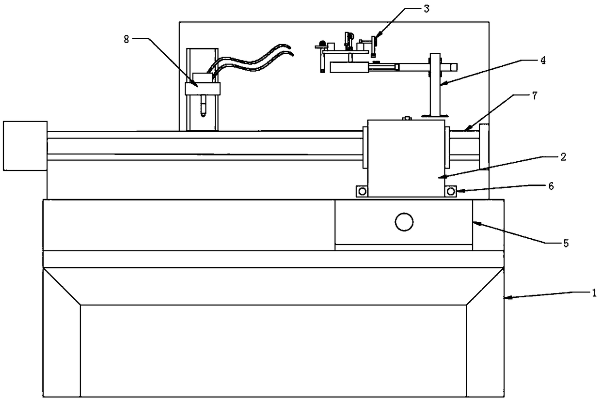
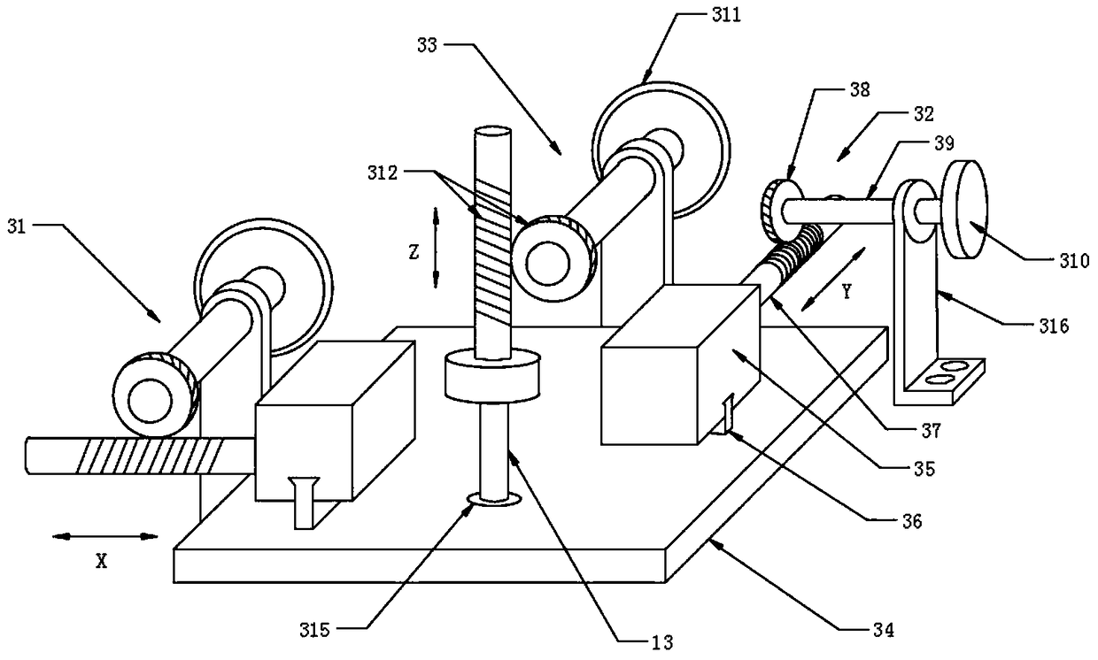
The invention discloses a blow molding machine. The blow molding machine comprises a frame, a blow molding machine head, an electric sliding table, a mold, a bottleneck surplus cutting device, a three-axis adjusting frame for surplus cutter and a bottle bottom surplus breaking device; the electric sliding table is arranged horizontally on the frame; the bottleneck surplus cutting device is arranged above the mold, and comprises a telescopic cylinder, a rack, a gear, a rotating link, a cutter bar and a cutter head; the three-axis adjusting frame for surplus cutter comprises a base board, an X-axis adjustment component, an Y-axis adjustment component, and an Z-axis adjustment component; the bottle bottom surplus breaking device comprises a telescopic cylinder, a bracket, and a clamp plate. The blow molding machine provided by the invention realizes the circumferential resection of the surplus material of the plastic bottleneck by the rotation of the cutter head, the overall cutting efficiency is high, the plastic bottleneck is flat, and the product quality is high; the three-axis adjusting frame for surplus cutter can finely adjust the bottleneck surplus cutting device to change theangle and direction of the cutter head to make the plastic bottleneck flatness to be higher.

Description

technical field [0001] The invention relates to the technical field of blow molding equipment, in particular to a blow molding machine. Background technique [0002] The production of plastic bottles is usually completed by a blow molding machine. After the molten plastic is extruded, it is blown in the mold. The contour of the plastic product is the contour of the molding groove of the mold. However, since the plastic product is usually formed by two molds, There will be mold joints in the middle of plastic products, especially when plastic bottles are filled with objects and dropped or hit, the mold joints at the bottom are easy to break; resulting in certain quality defects in plastic products. [0003] During the blow molding process of plastic bottles, especially after the mold has been blown out, there are usually scraps at the blowing port that need to be cut, that is, it is necessary to use a cutting knife to cut off the excess plastic on the upper end of the mold. I...

Claims


Application Information

Patent Timeline
Patent Type & Authority Applications(China)
IPC IPC(8): B29C49/42B29C37/02
CPCB29C49/4273B29C37/02B29C49/4278
Inventor 颜良志颜良进
Owner 武汉环岛塑胶包装有限责任公司
Learn More