
Rapid breaking device for medical ampoule bottles

An ampoule bottle, fast technology, applied in the direction of electric operation device, application, packaging, etc., can solve the problems of troublesome operation, easy to cause infection, easy to hurt the bottle head and fingers of nursing staff, etc., to achieve simple operation and convenient collection of bottle heads. Effect

Active Publication Date: 2020-11-06
王秀兰
View PDF8 Cites 4 Cited by
  • Summary
  • Abstract
  • Description
  • Claims
  • Application Information

AI Technical Summary

Problems solved by technology

[0005] In order to overcome the disadvantages that when many ampoules need to be broken off, the operation is cumbersome, and the broken head of the bottle can easily hurt the fingers of the nursing staff and easily cause infection. The technical problem is to provide a convenient bottle that can handle multiple bottles simultaneously. Head-collecting medical ampoules snap-off device

Method used


Image

  • Rapid breaking device for medical ampoule bottles
  • Rapid breaking device for medical ampoule bottles
  • Rapid breaking device for medical ampoule bottles

Examples


Embodiment 1

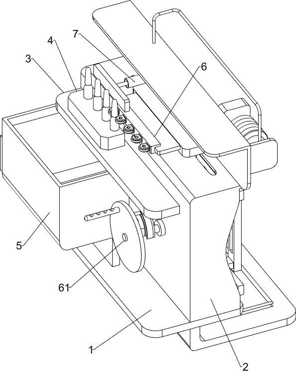
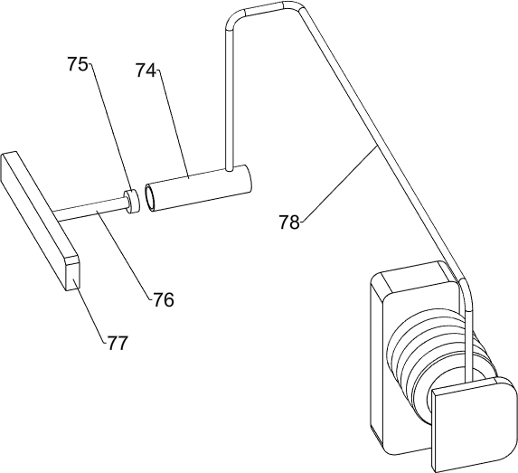
[0025] Such as Figure 1-4 As shown, a medical ampoule quick breaking device includes a base 1, a mounting frame 2, a fixing plate 3, a placement sleeve 4, a collection frame 5, a polishing device 6 and a pushing device 7, and the rear side of the top of the base 1 is provided with a mounting Frame 2, the upper part of the front side wall of the mounting frame 2 is provided with a fixed plate 3, the left side of the top of the fixed plate 3 is provided with a placement sleeve 4, the front left of the top of the base 1 is provided with a collection frame 5, and the mounting frame 2 is provided with a pair of ampoules A grinding device 6 for sliding cutting at the end, and a pushing device 7 for turning the end of the ampoule bottle is provided on the mounting frame 2 .

[0026] The grinding device 6 includes a rotating shaft 61, a rotating disk 62, a first sliding shaft 63, a fixed shaft 64, a folding groove plate 65, a sliding plate 67, a swing lever 68, an N-shaped clamping p...

Embodiment 2

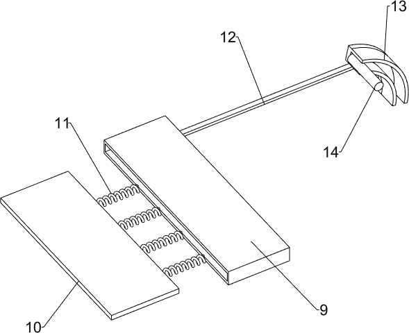
[0030] On the basis of Example 1, such as Figure 5-7 As shown, it also includes a slant plate 8, a square sleeve box 9, a baffle plate 10, a second elastic member 11, a moving rod 12, an arc guide rail 13, a sliding push rod 14 and a sliding collection box 15, and the left side of the collection frame 5 The upper part of the wall is provided with a slant plate 8, and the upper part of the right side wall in the collection frame 5 is provided with a square box 9, and the square box 9 is provided with a baffle 10 slidingly, and a second Two elastic parts 11, the second elastic part 11 is a compression spring, and the rear part of the right side wall of the collection frame 5 is slidingly provided with a moving rod 12, the left end of the moving rod 12 is fixedly connected with the baffle plate 10, and the right end of the moving rod 12 is provided with an arc Shaped guide rail 13, disc 611 rear side eccentric position is provided with sliding ejector pin 14, and sliding ejector...


PUM


Abstract

The invention belongs to the technical field of medical equipment, and particularly relates to a rapid breaking device for medical ampoule bottles. According to the rapid breaking device for the medical ampoule bottles, multiple bottles can be treated synchronously, and the collection of bottle heads is facilitated. According to the technical scheme, the rapid breaking device for the medical ampoule bottles comprises a base, a fixing plate, a placing sleeve, a collecting frame, a grinding device and a pushing device, wherein an installation frame is arranged on one side of the top of the base;the fixing plate is arranged on the upper part of the straight side wall of the installation frame; the placing sleeve is arranged on the fixing plate; the collecting frame is arranged at the position, close to the placing sleeve, of the top of the base; the grinding device for slidably cutting the ends of the ampoule bottles is arranged on the installation frame; and the pushing device for breaking off the ends of the ampoule bottles is arranged on the installation frame. According to the rapid breaking device, the effects that the multiple bottles can be treated synchronously, and the collection of the bottle heads is facilitated are achieved.

Description

technical field [0001] The invention belongs to the technical field of medical equipment, and in particular relates to a quick breaking device for medical ampoule bottles. Background technique [0002] Ampoule is a small glass container used to hold liquid medicine. The capacity is generally 1-25ml. It is often used to store injection medicine, and also used for oral liquid packaging. Modern ampoules are fired in glass tubes, and are widely used to contain injection preparations and high-purity chemicals that must be isolated from air. The nipple of the ampoule is sealed with an open flame to insulate the air, and the neck of the bottle is marked. When pressure is applied, the neck of the bottle will snap off so that the liquid medicine can be extracted. [0003] At present, the nurses first cut the neck of the ampoule bottle with a grinding wheel, and then manually break off the bottle head. When more ampoules need to be broken off, the operation is more troublesome, and ...

Claims


Application Information

Patent Timeline
Patent Type & Authority Applications(China)
IPC IPC(8): B67B7/92B65F1/14
CPCB67B7/92B65F1/14
Inventor 陈禄秀
Owner 王秀兰
Learn More