
An ampoule opener

A technology of ampoules and openers, which is applied in the field of medical appliances, can solve problems such as difficult operation, inconvenient operation, and easy cuts, and achieve the effects of strong applicability, simple operation, and multiple functions

Inactive Publication Date: 2020-11-27
THE SECOND AFFILIATED HOSPITAL ARMY MEDICAL UNIV
View PDF15 Cites 0 Cited by
  • Summary
  • Abstract
  • Description
  • Claims
  • Application Information

AI Technical Summary

Problems solved by technology

The capacity is generally 1 ~ 25ml, often used to store injection liquid, also used in the packaging of oral liquid, is a common medical liquid storage supplies; modern ampoules are fired with glass tubes, due to the relatively high High airtightness, can effectively isolate the air, and is widely used in containing injection preparations and high-purity chemicals that must be isolated from the air; however, the opening of the existing ampoule bottle is not easy to operate. The top of the ampoule is tapped quickly to break off the top of the ampoule, so as to obtain the liquid medicine in the bottle. However, this operation method will vary due to individual differences in ampoule bottles and the operator's personal experience; it is obviously not a scientific opening method Therefore, there have been openers for auxiliary opening on the market, and most of the existing openers are to clamp the ampoule bottle, and then it is convenient for the operator to break it off. This makes the operator need to be extra careful, so as not to accidentally injure himself by touching the mouth of the bottle when breaking it off; this method makes the existing ampoule bottle opener inconvenient to operate, improper use and easy to cut.

Method used


Image

  • An ampoule opener
  • An ampoule opener
  • An ampoule opener

Examples


Embodiment Construction

[0021] In order to make the above objects, features and advantages of the present invention more comprehensible, specific implementations of the present invention will be described in detail below in conjunction with the accompanying drawings. In the following description, numerous specific details are set forth in order to provide a thorough understanding of the present invention. However, the present invention can be implemented in many other ways different from those described here, and those skilled in the art can make similar improvements without departing from the connotation of the present invention, so the present invention is not limited by the specific implementations disclosed below.

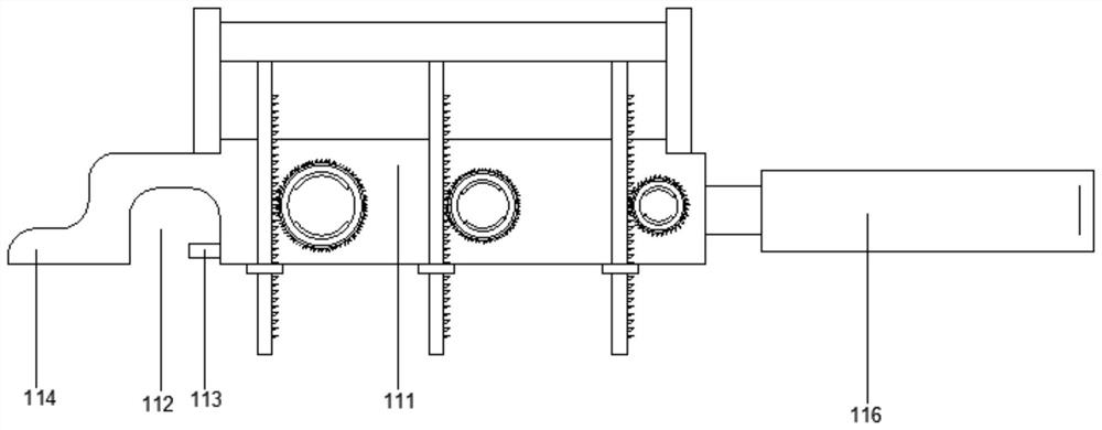
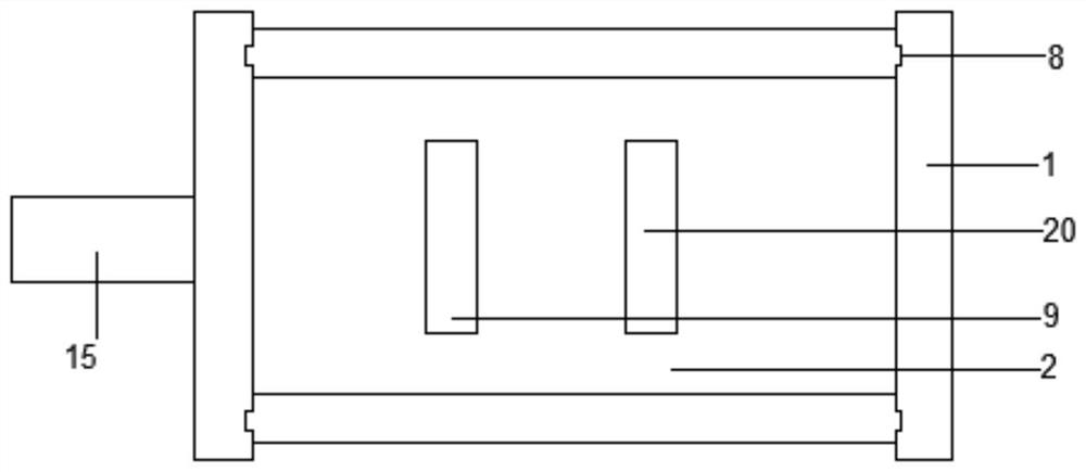
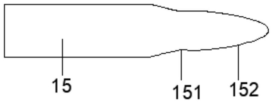
[0022] Attached below Figure 1-4 To further explain the present invention, an ampoule bottle opener includes a box body 1, and the box body 1 is provided with at least two opening mechanisms of different high specifications; thus, the opening mechanism of different specifications can...


PUM


Abstract

The invention relates to the technical field of medical utensils, in particular to an ampoule bottle opener. The ampoule bottle opener comprises a box, and two or more opening mechanisms with different high-specifications are arranged in the box; each opening mechanism comprises a moving plate, a rotating cylinder, a sand sheet, a tooth plate, a spring A, a fixed plate and a push block; a slidinggroove matched with the moving plate is formed in the inner side of the box, and the tooth plate is fixed to the bottom of the moving plate; a sand sheet key hole and a push rod key hole are formed inthe moving plate; an annular clamping groove is formed in the side, close to the bottom, of the box, the rotating cylinder is clamped through the annular clamping groove, and the fixed plate inside the box is matched with the annular clamping groove to fix the rotating cylinder; a gear sleeves the rotating cylinder and is matched with the tooth plate; a positioning rubber ring is arranged on theinner side of the rotating cylinder, and an ampoule bottle is clamped through the positioning rubber ring; and a spring is arranged between the fixed plate and the moving plate. The ampoule bottle opener has the characteristics of easy operation, diverse function and high applicability.

Description

technical field [0001] The invention relates to the technical field of medical appliances, in particular to an ampoule bottle opener. Background technique [0002] Ampoules are small glass containers used to hold liquid medicines. The capacity is generally 1 ~ 25ml, often used to store injection liquid, also used in the packaging of oral liquid, is a common medical liquid storage supplies; modern ampoules are fired with glass tubes, due to the relatively high High airtightness, can effectively isolate the air, and is widely used in containing injection preparations and high-purity chemicals that must be isolated from the air; however, the opening of the existing ampoule bottle is not easy to operate. The top of the ampoule is tapped quickly to break off the top of the ampoule, so as to obtain the liquid medicine in the bottle. However, this operation method will vary due to individual differences in ampoule bottles and the operator's personal experience; it is obviously not...

Claims


Application Information

Patent Timeline
Patent Type & Authority Patents(China)
IPC IPC(8): B67B7/92
CPCB67B7/92
Inventor 黄陈梁馨予王建李利白倩
Owner THE SECOND AFFILIATED HOSPITAL ARMY MEDICAL UNIV
Learn More