
PPR pipe hot melting machine

A hot-melting machine and pipe technology, applied in the direction of tubular articles, other household appliances, household appliances, etc., can solve the problems of low manual connection efficiency, difficult to guarantee connection quality, affecting work progress, etc., so as to improve the welding efficiency and ensure the welding quality. , the effect of precise docking

Inactive Publication Date: 2018-11-02
王佳颖
View PDF1 Cites 13 Cited by
  • Summary
  • Abstract
  • Description
  • Claims
  • Application Information

AI Technical Summary

Problems solved by technology

Since most of the existing hot melters are equipped with temperature controllers, the aforementioned problems of pipe heating temperature and time can be solved. However, the connection of pipes after heating still needs manual operation, and the quality of the connection is difficult to guarantee, and the efficiency of manual connection is low, which affects the work. schedule

Method used


Image

  • PPR pipe hot melting machine
  • PPR pipe hot melting machine
  • PPR pipe hot melting machine

Examples


Embodiment 1

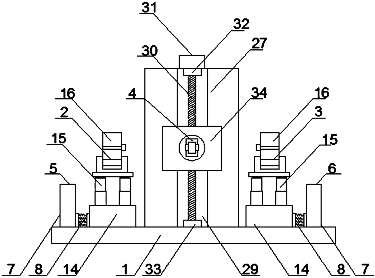
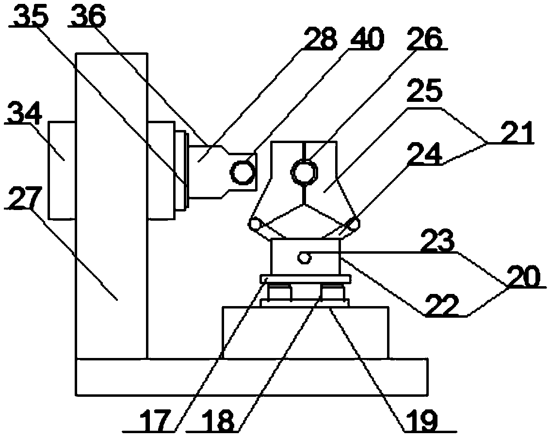
[0024] Such as figure 1 and figure 2 As shown, a PPR pipe hot-melt machine includes a platform 1, a first clamping mechanism 2, a second clamping mechanism 3, and a hot-melt mechanism 4; the first clamping mechanism 2 and the second clamping mechanism 3 are arranged on the platform 1 and located between the first limit mechanism 5 and the second limit mechanism 6, the two are oppositely arranged, wherein the first clamping mechanism 2 is close to the first limit mechanism 5, and the second clamping mechanism 3 is close to the second limit mechanism The position mechanism 6; the hot-melt mechanism 4 is arranged on the platform 1 and located between the first clamping mechanism 2 and the second clamping mechanism 3 .

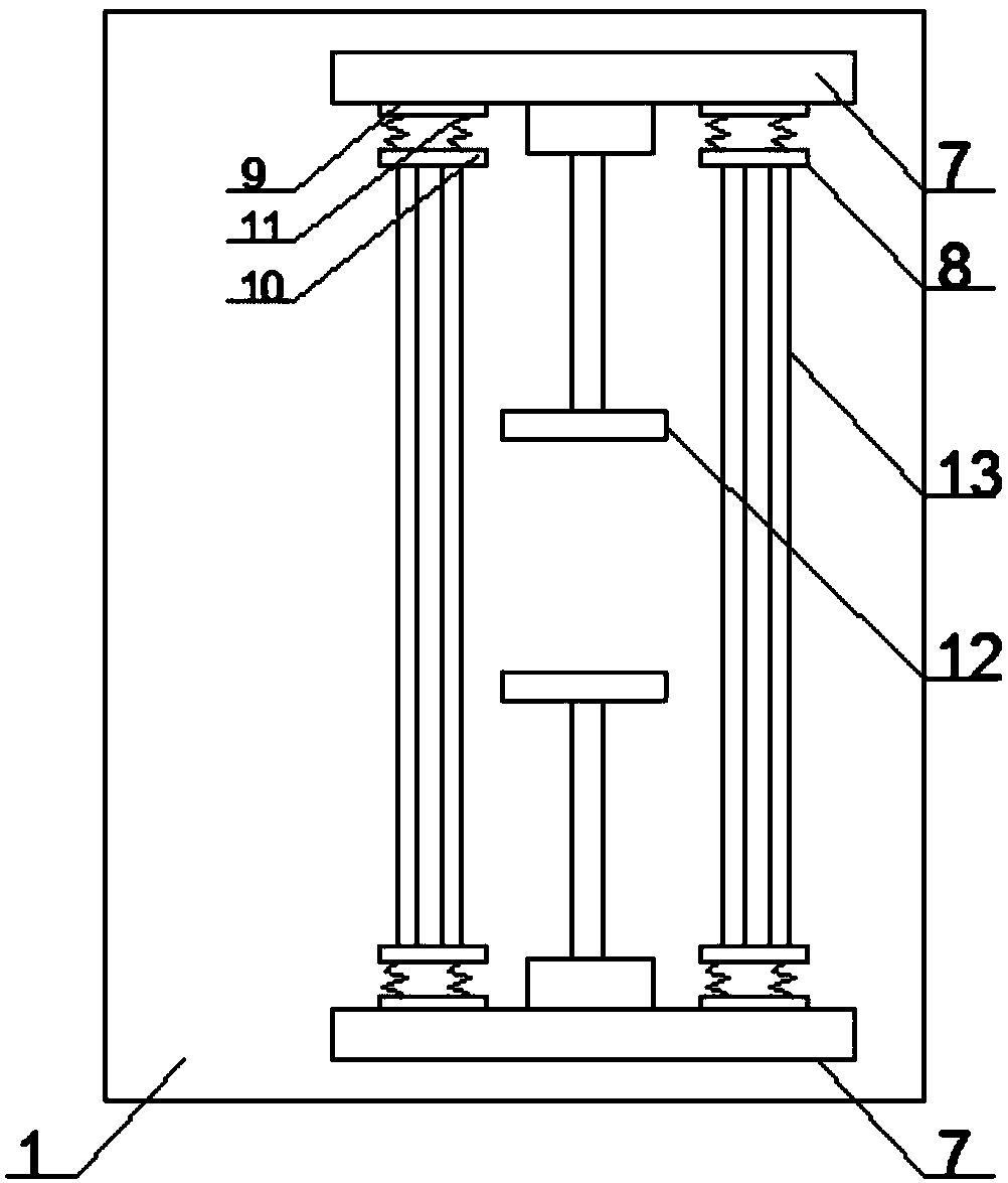
[0025] Such as image 3 As shown, the platform 1 is provided with a first limiting mechanism 5 and a second limiting mechanism 6, the first limiting mechanism 5 and the second limiting mechanism 6 all include a limiting plate 7 and a buffer pad 8, and the buffe...

Embodiment 2

[0030] Such as figure 1 and Figure 5 As shown, a PPR pipe hot-melt machine includes a platform 1, a first clamping mechanism 2, a second clamping mechanism 3, and a hot-melt mechanism 4; the first clamping mechanism 2 and the second clamping mechanism 3 are arranged on the platform 1 and located between the first limit mechanism 5 and the second limit mechanism 6, the two are oppositely arranged, wherein the first clamping mechanism 2 is close to the first limit mechanism 5, and the second clamping mechanism 3 is close to the second limit mechanism The position mechanism 6; the hot-melt mechanism 4 is arranged on the platform 1 and located between the first clamping mechanism 2 and the second clamping mechanism 3 .

[0031] Such as image 3 As shown, the platform 1 is provided with a first limiting mechanism 5 and a second limiting mechanism 6, the first limiting mechanism 5 and the second limiting mechanism 6 all include a limiting plate 7 and a buffer pad 8, and the buffe...


PUM


Abstract

The invention discloses a PPR pipe hot melting machine, and relates to the field of pipe connecting equipment. The PPR pipe hot melting machine comprises a platform, a first clamping mechanism, a second clamping mechanism and a hot melting mechanism; the first clamping mechanism and the second clamping mechanism are arranged on the platform, are positioned between a first limiting mechanism and asecond limiting mechanism, and are oppositely arranged, wherein the first clamping mechanism is near the first limiting mechanism, and the second clamping mechanism is near the second limiting mechanism; and the hot melting mechanism is arranged on the platform, and is positioned between the first clamping mechanism and the second clamping mechanism. The PPR pipe hot melting machine realizes mechanical operation of PPR pipe hot melting, can realize precise butt joint of PPR pipes, guarantees the pipe melting quality, and improves the melting efficiency.

Description

technical field [0001] The invention relates to the field of pipe connection equipment, in particular to a PPR pipe hot-melt machine. Background technique [0002] PPR pipe, that is, three-type polypropylene pipe, has the advantages of energy saving and material saving, environmental protection, light weight and high strength, corrosion resistance, smooth inner wall without scaling, easy construction and maintenance, and long service life. It is widely used in building water supply and drainage, urban and rural water supply and drainage, City gas, electric power and optical cable sheathing, industrial fluid transportation, agricultural irrigation and other construction, municipal, industrial and agricultural fields. PPR pipes usually need to be connected between pipes and pipes during installation and use, and the commonly used connection method is the hot melt method. The pipes connected by hot-melt method have high airtightness without losing the durability of PPR pipes. ...

Claims


Application Information

Patent Timeline
IPC IPC(8): B29C65/20B29C65/78B29L23/00
CPCB29C65/20B29C65/7841B29C66/5221B29C66/80B29L2023/22
Inventor 王佳颖
Owner 王佳颖
Learn More