Detergent putting structure and washing machine

A detergent injection and washing drum technology, applied in the field of washing machines, can solve the problems of easy water storage in pipelines and water outlets, and achieve the effects of easy market promotion, low failure probability, and strong feasibility

Inactive Publication Date: 2018-11-02
QINGDAO HAIER DRUM WASHING MACHINE
View PDF8 Cites 15 Cited by
  • Summary
  • Abstract
  • Description
  • Claims
  • Application Information

AI Technical Summary

Problems solved by technology

[0007] The primary purpose of the present invention is to provide a detergent dosing structure, which can effectively solve the defect that water is easy to accumulate in the pipes and water outlets inside the dosing device in the prior art, and the detergent described in the present invention The structure of the feeding structure is simple, the internal structure of the washing machine is simplified, the probability of failure of the washing machine is reduced, and the production and research and development costs of the washing machine are reduced at the same time. The market prospect is promising

Method used


Image

  • Detergent putting structure and washing machine
  • Detergent putting structure and washing machine

Examples


Embodiment 1

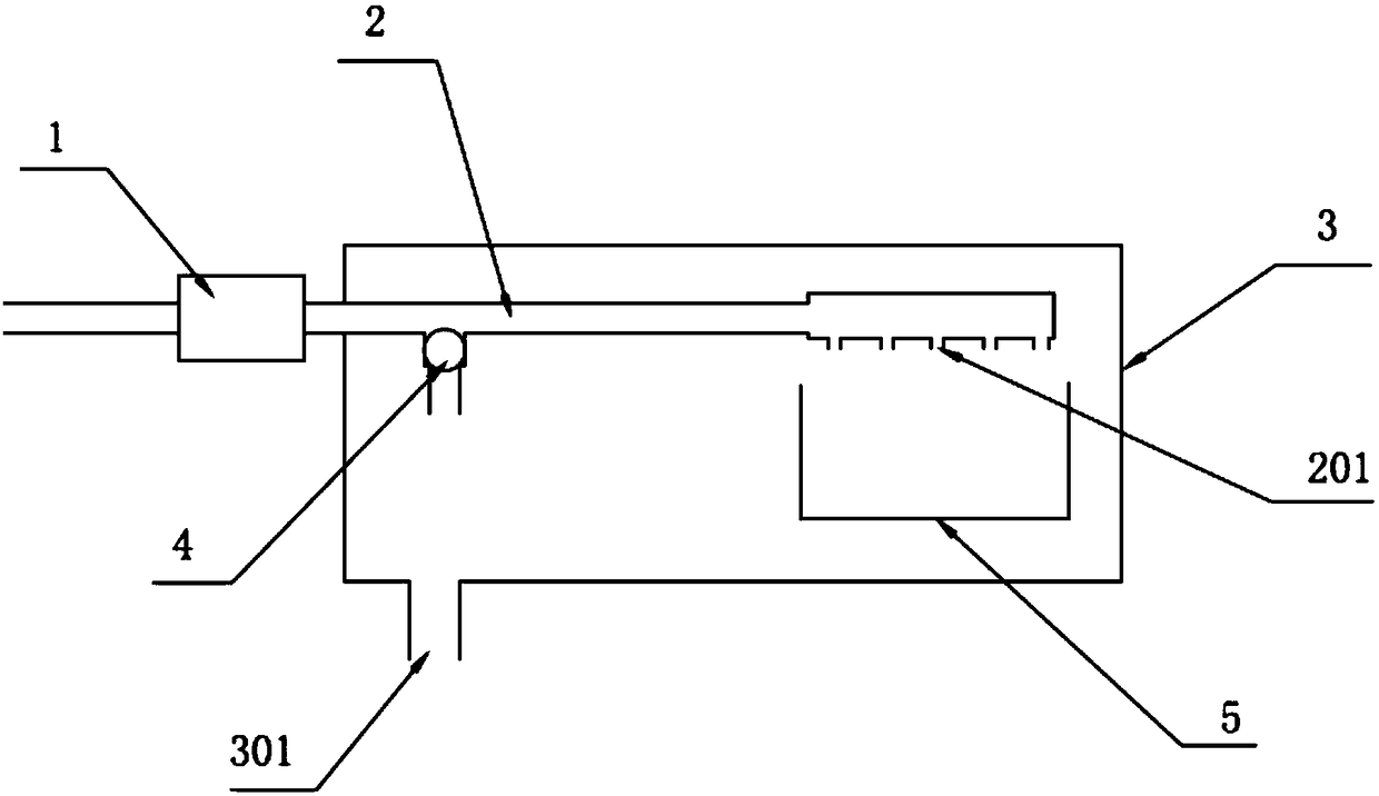
[0037] A detergent dispensing structure, comprising a water inlet valve 1, a water inlet pipeline 2 and a dispensing device 3, one end of the water inlet pipeline 2 is connected to the water outlet of the water inlet valve 1, and the other end extends to the inside of the dispensing device 3 and is provided with Waterway exit 201;

[0038] A ventilation structure located inside the dispensing device 3 is provided between the water inlet valve 1 and the waterway outlet 201. The ventilation structure uses the hydraulic pressure difference formed when the water inlet valve 1 is closed to empty the water in the water inlet pipeline 2 and the waterway outlet 201.

[0039] In the ventilation structure, the ventilation channel is closed when the water inlet valve 1 is opened, and the ventilation channel is opened when the water inlet valve 1 is closed, or the ventilation channel remains normally open.

[0040] The ventilation structure is a one-way check valve 4 or an air vent 6, and...

Embodiment 2

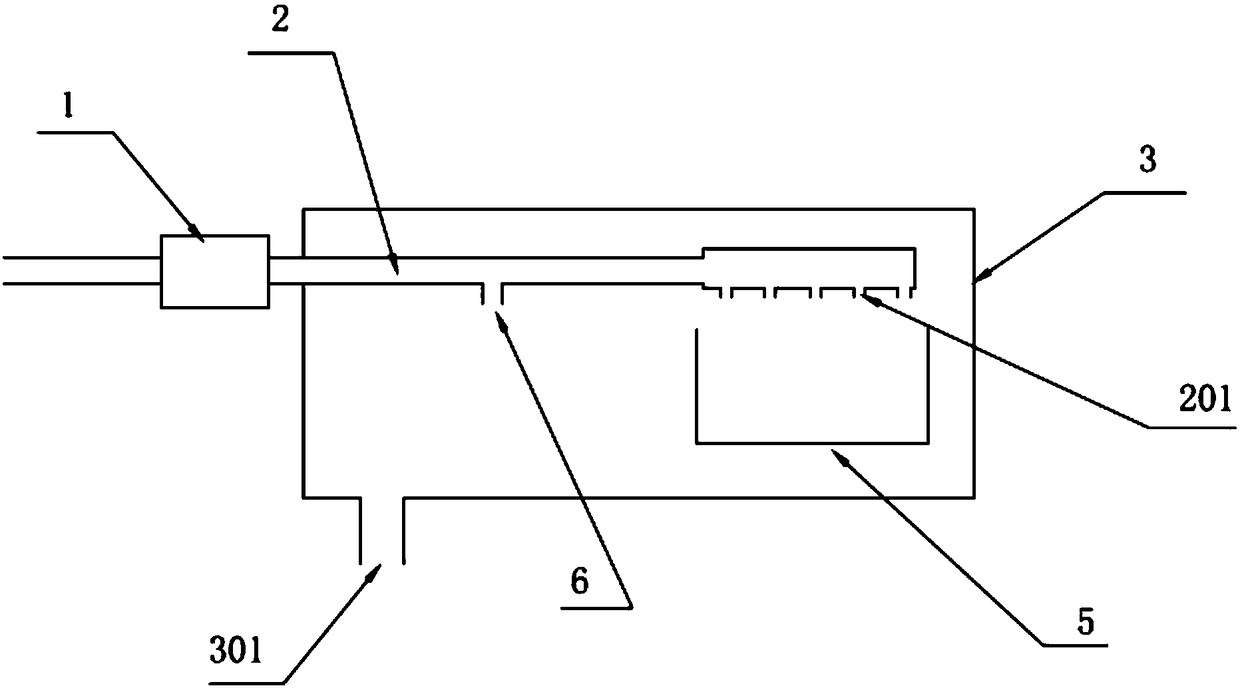
[0058] The difference between this embodiment and Embodiment 1 is that the ventilation structure is different, and the ventilation structure adopted in this implementation is the ventilation port 6, see the attached figure 2 .

[0059] A detergent dispensing structure, comprising a water inlet valve 1, a water inlet pipeline 2 and a dispensing device 3, one end of the water inlet pipeline 2 is connected to the water outlet of the water inlet valve 1, and the other end extends to the inside of the dispensing device 3 and is provided with Waterway exit 201;

[0060] A ventilation structure located inside the dispensing device 3 is provided between the water inlet valve 1 and the waterway outlet 201. The ventilation structure uses the hydraulic pressure difference formed when the water inlet valve 1 is closed to empty the water in the water inlet pipeline 2 and the waterway outlet 201.

[0061] In the ventilation structure, the ventilation channel is closed when the water inlet...


PUM


Abstract

The invention belongs to the technical field of washing machines and particularly relates to a detergent putting structure and a washing machine. The detergent putting structure comprises a water inlet valve, a water inlet pipeline and a putting device, wherein one end of the water inlet pipeline is connected to the water outlet of the water inlet valve, and the other end of the water inlet pipeline extends into the putting device and is provided with a water outlet part; a ventilation structure is disposed on the portion, between the water inlet valve and the water outlet part, of the interior of the putting device and uses hydraulic pressure difference formed when the water inlet valve is closed for draining water remaining in the water inlet pipeline and the water outlet part. The detergent putting structure can effectively overcome the defect that water easily remains in pipes and water outlet parts in putting devices; the structure is simple, the occurrence probability of faults of the washing machine is decreased, costs for production, research and development of the washing machine are reduced at the same time, and a promising market prospect is achieved.

Description

technical field [0001] The invention belongs to the technical field of washing machines, and in particular relates to a detergent feeding structure and a washing machine. Background technique [0002] The feeding device of the washing machine is usually equipped with a water inlet pipeline and a water outlet to realize the flushing and feeding of the corresponding detergent or detergent additive. After the water inlet valve is closed, because the cavity is a relatively sealed structure, the inside of the feeding device There will be a lot of residual water in the water inlet pipeline or the water outlet. Therefore, the feeding structure of the prior art has the following problems: [0003] 1. When the outdoor temperature is low, the water remaining in the water inlet pipe or water outlet of the delivery device will freeze, expand in volume, and easily crack the pipe. After the ice melts, it will cause water leakage and water seepage when water is fed again. ; [0004] 2. T...

Claims


Application Information

Patent Timeline
Patent Type & Authority Applications(China)
IPC IPC(8): D06F39/02D06F39/08
CPCD06F39/02D06F39/022
Inventor 吕佩师李丽平黄涛
Owner QINGDAO HAIER DRUM WASHING MACHINE
Why Eureka
Try Eureka