
Mortise without load generation in bolt opseration

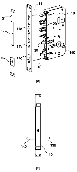
A doorbolt and mortise lock technology, which is applied in non-mechanical transmission-operated locks, building locks, locks, etc., can solve problems such as longer operating time, easy repair and damage of sub-locks, and decreased function of sub-locks. Stable, prevent the bolt from getting stuck, and ensure the effect of locking function

Active Publication Date: 2018-11-02
INNO ELECTRIC INC
View PDF9 Cites 3 Cited by
  • Summary
  • Abstract
  • Description
  • Claims
  • Application Information

AI Technical Summary

Problems solved by technology

[0011] Therefore, when the mortise lock is assembled or the mortise lock is installed on the door, the separate shafts should be inserted according to the indoor and indoor purposes. Since the accessories driven by each shaft are different, the lock that drives the bolt and deadbolt Escape can only be realized by linking each shaft correctly on the dead wheel and the bolt cam. If there are no other accessories with simple link structure on each shaft of the existing bolt lock and each cam, care must be taken when assembling the shaft. In this way, the assembly and installation of the bolt lock will become easier Difficult to obtain and longer to operate
[0012] In addition, in order to solve the problems in the prior art 2, a mortise lock (hereinafter referred to as prior art 3) is currently being developed, which increases the contact of the door lock buckle to enter and eject the sub-lock, and restricts the locking of the bolt. Furthermore, when the mortise lock shown in prior art 3 is in the closed state of the door, the sub-lock will not pop out completely through contact with the door lock when the door is closed, but a part of it will pop out, that is, a semi-protruding state. When the door is opened At the same time, when the sub-lock is fully ejected, it will be ejected again. At the same time, when the direction is switched, an impact will be generated. In this way, the sub-lock is easy to repair problems such as damage or the function of the sub-lock.

Method used


Image

  • Mortise without load generation in bolt opseration
  • Mortise without load generation in bolt opseration
  • Mortise without load generation in bolt opseration

Examples


Embodiment Construction

[0067] Hereinafter, the present invention will be further described based on preferred embodiments with reference to the accompanying drawings. The present invention can have various changes and forms, but it will not limit the form of the present invention. All changes, equivalents and even substitutes belonging to the idea and technical scope of the present invention are within the protection scope of the present invention.

[0068] The same reference symbols on the drawings, especially, tens digits and one digits or the same symbols of tens digits, one digits and English letters indicate the same or similar function accessories. If there is no special statement, the drawings indicate The symbol can be regarded as an accessory specified in accordance with the above requirements.

[0069] In addition, for the convenience of understanding, various components on the drawings are enlarged (thick) or reduced (thin), but this approach is not intended to limit the protection scope ...


PUM


Abstract

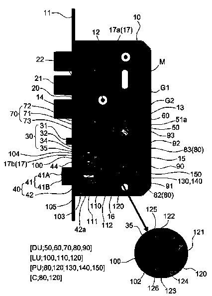
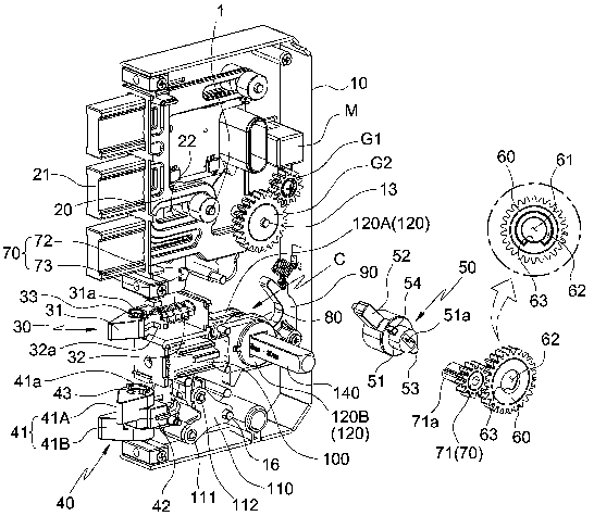
The invention provides a mortise without load generation in bolt operation. The mortise includes a deadbolt a sub latch, a main latch, and a deadbolt operation unit to lock and unlock a door. In particular, a deadbolt operation member and a driven gear are coupled to be able to rotate by using a guide groove so that a locking protrusion and a pressing protrusion part are separated from each otheron opposite sides, and the mortise includes a control means to control a motor in order to allow the driven gear to operate the deadbolt operation member and then to be returned to an original position thereof. Accordingly, when the deadbolt is locked and unlocked manually by using a key or a handle, or through operation of the motor by an input of a password, the deadbolt operation member or thedriven gear is rotated at first in a non-load state, thereby smoothly performing locking and unlocking operations of the deadbolt.

Description

technical field [0001] The invention provides a mortise lock that does not generate load when the bolt operates, including a deadbolt sub-lock for locking and unlocking the door, a deadbolt, and a bolt operating unit. More specifically, it includes a controller, through which the bolt operating member The rotation of the driven gear keeps a certain distance between the clamping block and the pressure protruding piece. After the driven gear drives the bolt operating member, the driven gear returns to its original position through the control of the motor. Locking or unlocking the bolt by the key or the handle, or through the action of the motor such as password input, when the bolt is locked and unlocked, the bolt operating member or the driven gear rotates under no-load conditions to realize the bolt's movement. Locking and unlocking action. Background technique [0002] Smart door locks are used on different doors such as hallways, offices, and warehouses of ordinary famil...

Claims


Application Information

Patent Timeline
Patent Type & Authority Applications(China)
IPC IPC(8): E05B47/00E05B63/14E05B15/00E05B3/00E05B49/00
Inventor 赵阳日
Owner INNO ELECTRIC INC
Learn More