High temperature resistant and shock-proof sensor

A high temperature resistant sensor technology, applied in the field of sensors, can solve the problems of thermal erosion of sensor elements, reduction of sensor measurement accuracy, damage of measurement board components, etc., achieve good heat insulation effect, avoid vibration shock damage, and improve measurement accuracy.

Inactive Publication Date: 2018-11-02
王凯丽
View PDF0 Cites 0 Cited by
  • Summary
  • Abstract
  • Description
  • Claims
  • Application Information

AI Technical Summary

Problems solved by technology

[0003] 1. The measuring tube of the oil level sensor in the prior art is generally a single-layer metal tube. When the oil temperature rises, it is easy to conduct high heat into the sensor, causing the components inside the sensor to be eroded by heat;
[0004] 2. When the vehicle is driving on a bumpy road, the sensor and the vehicle body vibrate at the same time. In the case of long-term vibration, the measuring board inside the sensor is not strong enough and the installation is not good, so it is easy to rotate or move in series, resulting in measurement The components on the board are damaged;
[0005] 3. The maglev below the sensor and the measuring tube tend to rotate relative to each other when the oil fluctuates and vibrates, causing the magnetic field generated by the magnetic poles in the maglev to change the position of the components on the measuring board, so the measurement is prone to deviation, resulting in the measurement of the sensor Reduced accuracy

Method used


Image

  • High temperature resistant and shock-proof sensor
  • High temperature resistant and shock-proof sensor
  • High temperature resistant and shock-proof sensor

Examples


Embodiment Construction

[0026] The following will clearly and completely describe the technical solutions in the embodiments of the present invention with reference to the accompanying drawings in the embodiments of the present invention. Obviously, the described embodiments are only some, not all, embodiments of the present invention. Based on the embodiments of the present invention, all other embodiments obtained by persons of ordinary skill in the art without making creative efforts belong to the protection scope of the present invention.

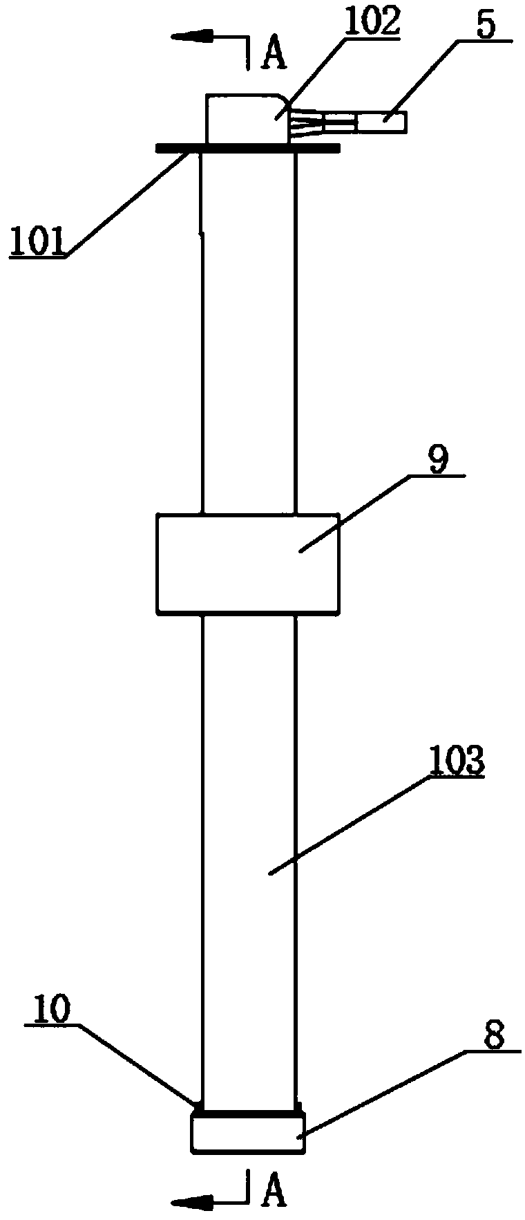
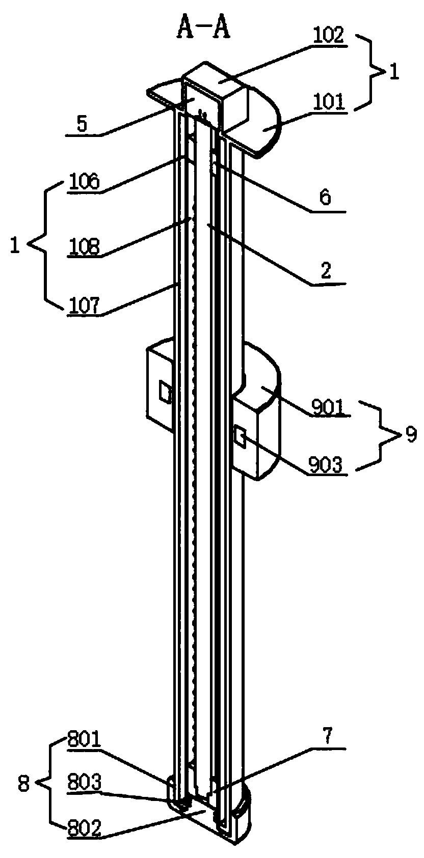
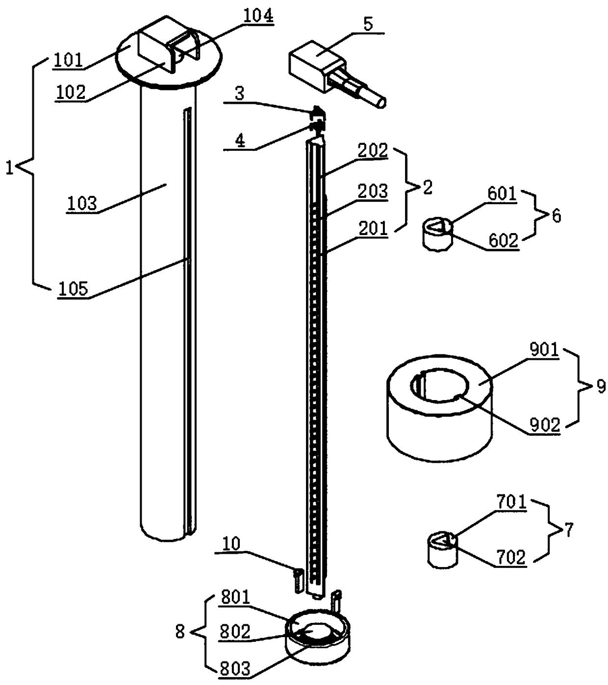
[0027] see Figure 1-5 , the present invention provides a technical solution: a high temperature resistant and shockproof sensor, including a mounting base 1, a measuring plate 2 matched and installed inside the mounting base 1, a locking cover 8 matched and installed at the lower end of the mounting base 1 and the outside of the mounting base 1 The matching maglev 9, the upper end of the mounting seat 1 is provided with a disc-shaped mounting plate 101, and t...


PUM


Abstract

The invention discloses a high temperature resistant and shock-proof sensor. The sensor comprises an installing base, a measuring plate installed in cooperation with the interior of the installing base, a locking cover installed in cooperation with the lower end of the installing base and a magnetic suspension cooperatively sleeving the installing base. An installing disc of the disc type structure is arranged at the upper end of the installing base, and a protective cover of a U-shaped shell structure is arranged at the upper end of the installing disc; an installing cylinder on the installing base is of a dual-layer cylinder structure composed of an inner cylinder and an outer cylinder, a vacuum heat insulation cavity of a sealing structure is formed between the inner cylinder and the outer cylinder, the interior of the whole installing hole has the good heat insulation effect, and the measuring plate inside the installing hole is protected against high temperature or corrosion; thebody of the measuring plate is a PCB of a triangular columnar structure, and due to the structure, the strength of the measuring plate is improved; due to multiple elastic fixing sleeves I and elasticfixing sleeves II sleeving in cooperation with the outer side faces of the upper and lower ends of the measuring plate, the whole measuring plate is well fixed, buffered and damped, and a magnetic reed on the measuring plate is protected against vibration or impact or damage.

Description

technical field [0001] The invention relates to the technical field of sensors, in particular to a high temperature resistant and shockproof sensor. Background technique [0002] In the fuel tank of the vehicle, the oil level in the fuel tank is generally measured by a liquid level sensor. The oil level sensor in the prior art has a relatively stable structure and is easy to install, but it still has the following disadvantages in actual use: [0003] 1. The measuring tube of the oil level sensor in the prior art is generally a single-layer metal tube. When the oil temperature rises, it is easy to conduct high heat into the sensor, causing the components inside the sensor to be eroded by heat; [0004] 2. When the vehicle is driving on a bumpy road, the sensor and the vehicle body vibrate at the same time. In the case of long-term vibration, the measuring board inside the sensor is not strong enough and the installation is not good, so it is easy to rotate or move in series,...

Claims


Application Information

Patent Timeline
Patent Type & Authority Applications(China)
IPC IPC(8): G01F23/62
CPCG01F23/62
Inventor 王凯丽何伯春王慧超
Owner 王凯丽
Why Eureka
Try Eureka