Microwave Electric Coupling Structure and Its Realization Method

A technology of electrical coupling and microwave, applied in the field of electronics, can solve the problem that the magnetic coupling structure is not easy to transmit zero points, etc., and achieve the effect of excellent out-of-band suppression characteristics, easy implementation, and high electrical coupling coefficient

Active Publication Date: 2020-07-24
ALCATEL LUCENT SHANGHAI BELL CO LTD
View PDF3 Cites 0 Cited by
  • Summary
  • Abstract
  • Description
  • Claims
  • Application Information

AI Technical Summary

Problems solved by technology

However, the magnetically coupled structure is not easy to achieve out-of-band transmission zero

Method used


Image

  • Microwave Electric Coupling Structure and Its Realization Method
  • Microwave Electric Coupling Structure and Its Realization Method
  • Microwave Electric Coupling Structure and Its Realization Method

Examples


Embodiment Construction

[0025] The present invention will be described in further detail below in conjunction with the accompanying drawings.

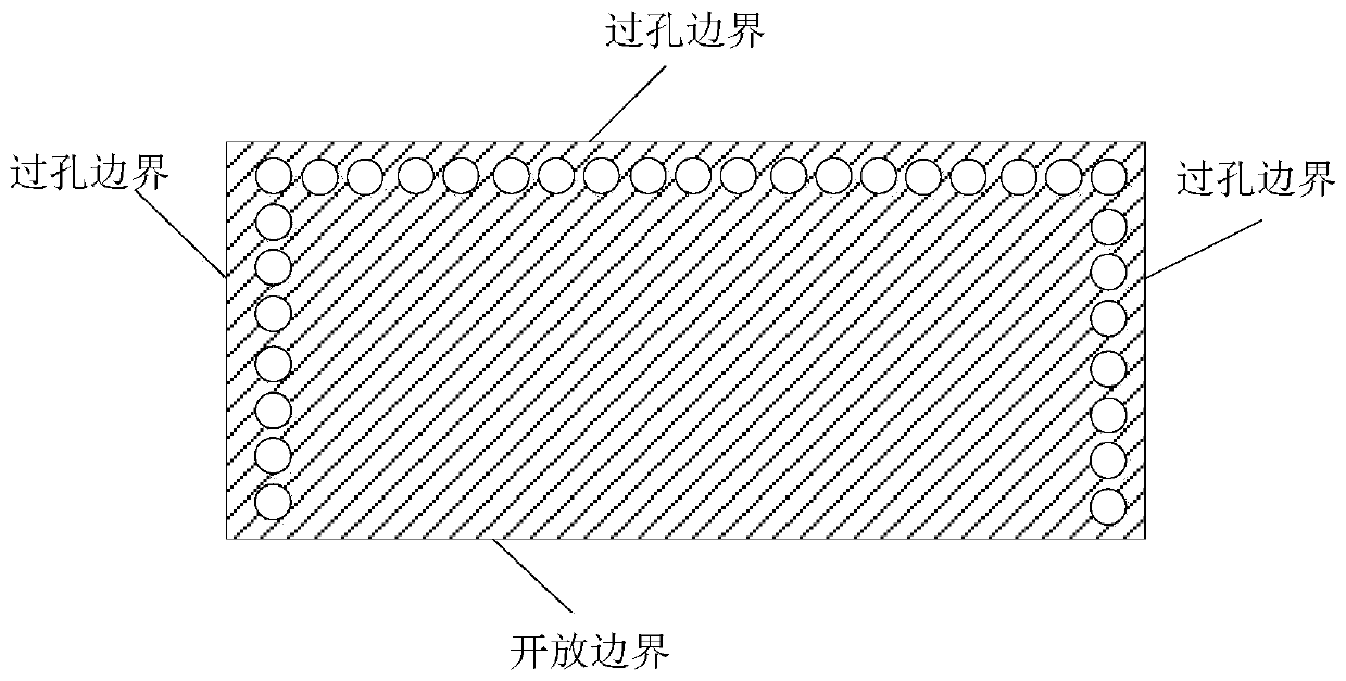
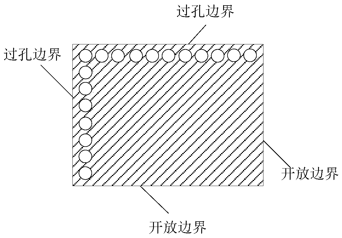
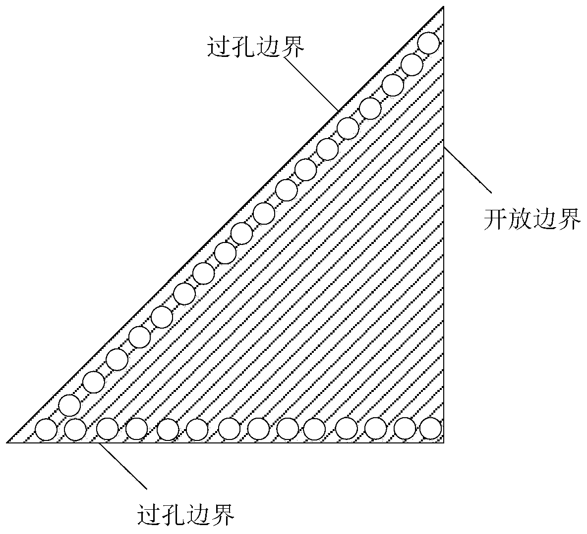
[0026] The microwave electrical coupling structure of the embodiment of the present invention can be applied to microwave devices such as filters, antennas, oscillators, couplers, etc. using substrate integrated waveguides, that is, can be applied to microwave circuits using these microwave devices. The substrate-integrated waveguide uses adjacent metallized through holes on the dielectric substrate to form an electric wall, and forms a structure similar to a common waveguide together with the upper and lower metal surfaces. The substrate-integrated waveguide resonator includes a metal top layer, a dielectric layer and a bottom layer. The metal vias of the resonator pass through the metal top layer, the dielectric layer and the bottom layer, and the bottom layer is all metallized to form an electrical ground. The metal used for metal vias, metal top layer an...


PUM


Abstract

The invention discloses an improved microwave electric coupling structure and an implementation method therefor. According to the microwave electric coupling structure, electric coupling between substrate integrated waveguides with open boundaries can be implemented; and a microwave device with a high performance index can be implemented when the microwave electric coupling structure is applied tothe devices, such as a filter, an oscillator, an antenna and a coupler.

Description

technical field [0001] The invention relates to the field of electronic technology, in particular to a microwave electric coupling structure and a realization method thereof. Background technique [0002] Ordinary waveguides are bulky and difficult to integrate. Substrate Integrated Waveguide (SIW for short) is a new type of microwave transmission structure. The substrate-integrated waveguide uses metallized through holes adjacent to each other to form an electric wall on the dielectric substrate, and together with the upper and lower metal surfaces, it forms a structure similar to an ordinary waveguide. Substrate-integrated waveguide is a transmission line between microstrip and dielectric-filled waveguide. It is small in size, easy to integrate, high in power capacity, low in loss, and low in cost. The substrate-integrated waveguide takes into account the advantages of waveguides and microstrip transmission lines, and can realize high-performance microwave and millimeter...

Claims


Application Information

Patent Timeline
Patent Type & Authority Patents(China)
IPC IPC(8): H01P1/20
CPCH01P1/20
Inventor 梅迪朱其玉喻鸿飞冯昀罗旭荣
Owner ALCATEL LUCENT SHANGHAI BELL CO LTD
Why Eureka
Try Eureka