Automatic cable stripping machine

A technology of automatic wire stripping and wire stripping mechanism, which is applied in the direction of dismantling/armoured cable equipment, etc., can solve the problems of removal, heavy stripping force, and high rate of defective products, so as to reduce production costs, shorten stripping time, The effect of improving the stripping quality

Pending Publication Date: 2018-11-02
CHANGZHOU INST OF LIGHT IND TECH
View PDF0 Cites 0 Cited by
  • Summary
  • Abstract
  • Description
  • Claims
  • Application Information

AI Technical Summary

Problems solved by technology

[0002] Pliers, knives or scissors are generally used to peel off the cable insulation layer. When using the above tools to peel off the cable insulation layer, all the force is used by the operator based on feeling, which can easily lead to too light peeling force and cannot be removed. Peeling, or the peeling force is too heavy so that the layer that does not need to be peeled is also removed, so the occurrence rate of defective products is high; in addition, for the operator, due to the low safety of the tool, improper operation is also likely to cause personal injury. cut
[0003] In order to solve the above problems, an automated wire stripping device is used in the prior art. The wire stripping device generally includes a fixing mechanism for fixing the cable, a knife set for cutting the outer insulating layer, and an off-line mechanism for pulling the knife set. The cable is fixed on the On the fixing mechanism, the insulation layer is cut off by the knife group, and then the stripping mechanism pulls the knife group to the side to remove the cut insulation layer from the cable mountain. The current stripping mechanism can only strip the cable on one side. Wire operation, can not achieve bilateral simultaneous stripping operation, stripping operation efficiency is low

Method used


Image

  • Automatic cable stripping machine
  • Automatic cable stripping machine
  • Automatic cable stripping machine

Examples


Embodiment 1

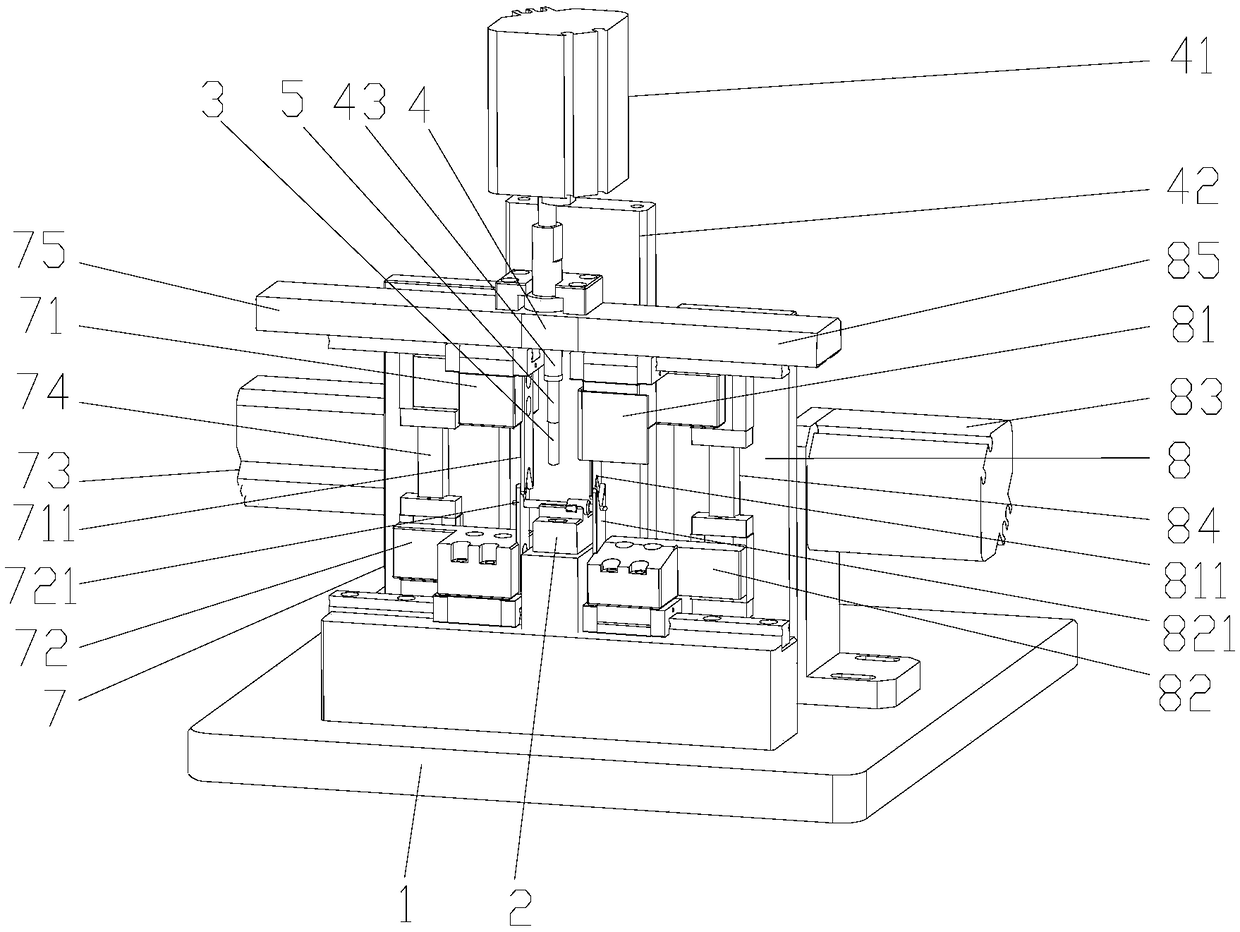
[0027] Embodiment 1: refer to figure 1 , an automatic wire stripping machine, including a machine 1 and a wire setting table 2 set on the machine 1 for placing cables. The upper surface of the wire setting table 2 is an arc structure that matches the external structure of the cable. Refer to Figure 5 , the upper surface of the wire setting table 2 is provided with a rubber layer 21, which increases friction, and at the same time provides cushioning, protects the cable, and prevents the cable from being crushed. The left stripping mechanism and the right stripping mechanism for stripping the cables on the top of the cable, and the upper side of the wire setting table 2 is provided with a crimping mechanism. Rod 3, pressing plate 4 on the upper part of pressing bar 3, vertical cylinder 41 that drives pressing plate 4 to move up and down, vertical support plate 42 is provided on the machine platform corresponding to the rear side of thread setting table 2, and vertical support p...

Embodiment 2

[0032] Embodiment 2: The difference between this embodiment and Embodiment 1 is that the limit mechanism 45 is different. In this embodiment, the limit mechanism 45 adopts a limit cylinder with a vertical output end upward, and the output of the limit cylinder The bottom end of the connecting rod is limited. When the connecting rod reaches the limit position, the connecting rod stops falling. Through the unloading mechanism composed of the unloading cylinder, the unloading spring and the connecting rod, a vertical cylinder is driven synchronously. Complete the cable positioning and stripping operations of the cutter components on both sides. The unloading mechanism enables the left stripping mechanism, the right stripping mechanism and the crimping mechanism to cooperate with each other without interference, so that the stripping machine has a high Productivity.

Embodiment 3

[0033] Embodiment 3: refer to Figure 4 , the difference between this embodiment and Embodiment 1 is: the difference between the left connecting mechanism and the right connecting mechanism. The left side of the left connecting plate 9 is embedded with a cavity 46, and the left pressing plate 75 is provided with a left connecting cavity 751 near the pressing plate 4. The left connecting plate 9 can be turned out of the left embedded cavity 46 and then embedded in the left connecting cavity 751 to realize the left pressing plate. 75. The connection between the pressing plates 4, the right connecting mechanism is the right connecting plate 91 hinged to the right side of the pressing plate 4, the right side of the pressing plate 4 is provided with a right embedded cavity 47 for fitting the right connecting plate 91, and the right pressing plate 85 is close to the pressing plate 7 is provided with a right connecting cavity 851, and the right connecting plate 91 can be turned out f...


PUM


Abstract

The invention relates to the technical field of cable outer layer stripping, and particularly relates to an automatic cable stripping machine. The automatic cable stripping machine comprises a machinestand and a machine stand cable placement table; a left cable stripping mechanism and a right cable stripping mechanism which are used for carrying out cable stripping on a cable on the cable placement table are respectively arranged at both sides of the cable placement table; a cable pressure mechanism is arranged at the upper side of the cable placement table; the cable pressure mechanism comprises a pressure rod, a pressure plate and a driving mechanism; the pressure rod is connected with the pressure plate by a connection rod; the bottom end of the connection rod sleeves the upper end ofthe pressure rod; a spring is arranged between the bottom end of the connection rod and the top end of the pressure rod; the top end of the connection rod is connected with the pressure plate by a force unloading mechanism; the force unloading mechanism comprises a force unloading barrel arranged at the bottom of the pressure plate and a force unloading spring inside the force unloading barrel; the upper end of the connection rod is embedded in the force unloading barrel and is in sliding fit with the inner wall of the force unloading barrel; the bottom end of the force unloading spring is pressed against the top end of the connection rod; and a limiting mechanism for limiting a descent height of the connection rod is arranged at the position of the cable placement table. The single-side or both-side simultaneous stripping operation of the cable is implemented, and production efficiency is high.

Description

technical field [0001] The invention relates to the technical field of cable outer layer stripping, in particular to an automatic wire stripping machine. Background technique [0002] Pliers, knives or scissors are generally used to peel off the cable insulation layer. When using the above tools to peel off the cable insulation layer, all the force is used by the operator based on feeling, which can easily lead to too light peeling force and cannot be removed. Peeling, or the peeling force is too heavy so that the layer that does not need to be peeled is also removed, so the occurrence rate of defective products is high; in addition, for the operator, due to the low safety of the tool, improper operation is also likely to cause personal injury. cut. [0003] In order to solve the above problems, an automated wire stripping device is used in the prior art. The wire stripping device generally includes a fixing mechanism for fixing the cable, a knife set for cutting the outer ...

Claims


Application Information

Patent Timeline
Patent Type & Authority Applications(China)
IPC IPC(8): H02G1/12
CPCH02G1/1256Y02W30/82
Inventor 苏素芹
Owner CHANGZHOU INST OF LIGHT IND TECH
Why Eureka
Try Eureka