
Firefighting equipment special for high-rise building

A technology for fire-fighting equipment and buildings, applied in building rescue and life-saving equipment, etc., can solve the problems that high-rise fire-fighting equipment does not have a size adjustment structure, users cannot use high-rise fire-fighting equipment, and reduce the scope of application of high-rise fire-fighting equipment. Increase the scope of application, the effect of fixing is good, and the effect of easy operation

Inactive Publication Date: 2018-11-06
叶彩英
View PDF0 Cites 3 Cited by
  • Summary
  • Abstract
  • Description
  • Claims
  • Application Information

AI Technical Summary

Problems solved by technology

[0002] The fire-fighting equipment used in high-rise buildings is a kind of high-altitude slow-down equipment for self-rescue and escape when a fire occurs in a high-rise building. Put the heavy shackle and tighten the wire rope. After the rescuer holds the brake handle, the escaper moves the body out of the wall, and the rescuer slowly releases the brake handle to make it fall vertically; The traditional high-rise fire-fighting equipment itself only has a single-weight fixed structure. When the user descends slowly through the high-rise fire-fighting equipment, it is easy to shake due to the wind in the building, which has certain safety hazards, and the traditional high-rise fire-fighting equipment itself is not good. It has a size-adjustable structure, which reduces the scope of application of high-rise fire-fighting equipment. Larger users cannot use high-rise fire-fighting equipment, which has a certain impact on users. Therefore, we propose a fire-fighting equipment dedicated to high-rise buildings. equipment

Method used


Image

  • Firefighting equipment special for high-rise building
  • Firefighting equipment special for high-rise building
  • Firefighting equipment special for high-rise building

Examples


Embodiment Construction

[0016] In order to make the technical means, creative features, goals and effects achieved by the present invention easy to understand, the present invention will be further described below in conjunction with specific embodiments.

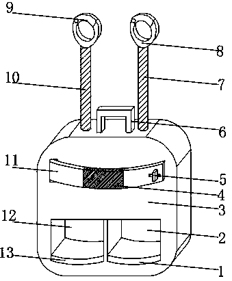
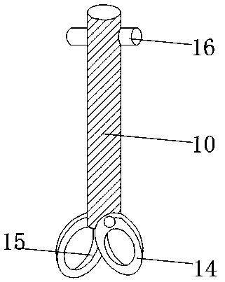
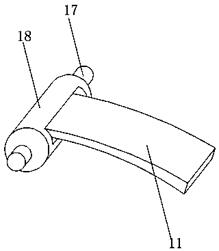
[0017] Such as Figure 1-3 As shown, a kind of fire-fighting equipment dedicated to high-rise buildings includes a high-rise escape device main body 3, a telescopic waist belt 11 is fixedly installed on the front outer surface of the high-rise escape device main body 3, and a telescopic belt 11 is fixedly installed in the middle of the outer surface of the telescopic waist belt 11. Elastic belt 4, the front end outer surface of telescopic waist belt 11 is movably installed with fixed buckle 5 near the side of elastic belt 4, and the front end inner surface of high-rise escape device main body 3 is provided with No. 2 fixing groove 12 near the bottom of telescopic waist belt 11, and high-rise escape The inner surface of the front end of the device ...


PUM


Abstract

The invention discloses firefighting equipment special for a high-rise building. The firefighting equipment special for the high-rise building comprises a high-rise escape device main body, the outersurface of the front end of the high-rise escape device main body is fixedly provided with a telescopic waistband, the middle of the outer surface of the telescopic waistband is fixedly provided withan elastic band, and the side, close to the elastic band, of the outer surface of the front end of the telescopic waistband is movably provided with a fixing buckle. A second fixing groove is formed below the position, close to the telescopic waistband, of the inner surface of the front end of the high-rise escape device main body, a first fixing groove is formed in the side, close to the second fixing groove, of the inner surface of the front end of the high-rise escape device main body, and the outer surface of the lower end of the first fixing groove is fixedly provided with a first shock pad. The firefighting equipment special for the high-rise building is provided with a second fixing rope and the telescopic waistband, the application range of the equipment can be effectively broadened, the safety of the equipment is improved, and better use prospect is brought.

Description

technical field [0001] The invention relates to the field of fire-fighting equipment, in particular to a fire-fighting equipment specially used for high-rise buildings. Background technique [0002] The fire-fighting equipment used in high-rise buildings is a kind of high-altitude slow-down equipment for self-rescue and escape when a fire occurs in a high-rise building. Put the heavy shackle and tighten the wire rope. After the rescuer holds the brake handle, the escaper moves the body out of the wall, and the rescuer slowly releases the brake handle to make it fall vertically; The traditional high-rise fire-fighting equipment itself only has a single-weight fixed structure. When the user descends slowly through the high-rise fire-fighting equipment, it is easy to shake due to the wind in the building, which has certain safety hazards, and the traditional high-rise fire-fighting equipment itself is not good. It has a size-adjustable structure, which reduces the scope of app...

Claims


Application Information

Patent Timeline
Patent Type & Authority Applications(China)
IPC IPC(8): A62B1/06A62B1/16A62B1/18
CPCA62B1/06A62B1/16A62B1/18
Inventor 叶彩英
Owner 叶彩英
Learn More