Smooth cutting equipment for petroleum pipeline

A technology for cutting equipment and oil pipelines, used in metal processing and other directions, can solve problems such as troublesome operation and uneven ports, and achieve the effect of ensuring smoothness

Inactive Publication Date: 2020-04-17
朱文科
View PDF9 Cites 4 Cited by
  • Summary
  • Abstract
  • Description
  • Claims
  • Application Information

AI Technical Summary

Problems solved by technology

[0002] my country's oil pipeline construction will usher in a new climax. At present, oil pipelines have become one of the main transportation tools for oil, and they still have considerable development potential in the future. The pipes of oil pipelines are generally steel pipes, which are connected by welding and flanges. The device connects long-distance pipelines. During the connection process, it is necessary to cut the specifications of the pipelines and cut them into sizes that meet the needs of the site. During the cutting process, the ports often appear uneven. When the end faces of the two pipelines are connected, There will be gaps, and it needs to be re-polished, which is troublesome to operate

Method used


Image

  • Smooth cutting equipment for petroleum pipeline
  • Smooth cutting equipment for petroleum pipeline
  • Smooth cutting equipment for petroleum pipeline

Examples


Embodiment 1

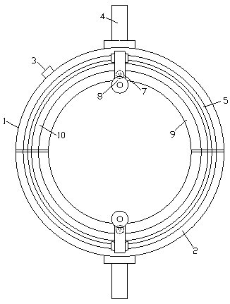
[0025] see Figure 1-Figure 4 , the present invention provides a technical solution for leveling and cutting equipment for oil pipelines: its structure consists of an upper deck 1 and a lower deck 2, the upper deck 1 and the lower deck 2 have the same structure and the two are fastened and connected , the upper card seat 1 is composed of a power connector 3, a handle 4, an arc-shaped slide rail 5, a rotating device 7, a cutting device 8, a ring road 9, and an arc-shaped ring gear 10. The handle 4 is connected to the upper card seat by bolts The top edge of 1 is threaded, and the upper deck 1 is connected with a power connector 3, and the top surface of the upper deck 1 is sequentially installed with an arc-shaped slide rail 5 and an arc-shaped ring gear 10. The cutting device 8 is engaged with the arc ring gear 10 and matches with the arc slide rail 5, and the inner side of the upper deck 1 is provided with a ring road 9, and the cutting device 8 is cut by a rotator 81, a chai...

Embodiment 2

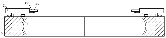
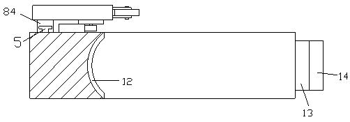
[0028] Such as image 3 and Figure 4 As shown, on the basis of Embodiment 1, a protruding shaft 13 is provided on both ends of the upper deck 1, and a second electromagnet 14 is connected to the protruding shaft 13, and the lower deck 2 Grooves 15 are provided on both ends of the groove 15, and a third electromagnet 16 is installed inside the groove 15, and the upper deck 1 and the lower deck 2 are engaged with each other through the protruding shaft 13 and the groove 15. Connect to form a circle.

[0029] The upper deck 1 and the lower deck 2 are connected together by buckling, the protruding shaft 13 on the upper deck 1 matches the groove 15 of the lower deck 2, and when the power connector 3 is energized, the second electromagnet 14 The third electromagnet 16 is energized to generate magnetism with opposite polarity, and the two attract each other, so that the upper deck 1 and the lower deck 2 are firmly fastened on the pipeline, preventing shaking during cutting.


PUM


Abstract

The invention discloses smooth cutting equipment for a petroleum pipeline. The smooth cutting equipment is characterized by structurally comprising an upper blocking base and a lower blocking base, wherein the upper blocking base and the lower blocking base are consistent in structure, and are in locking connection; and the upper blocking base consists of a power supply joint, a handle, arc-shapedslide rails, a rotary device, a cutting device, a ring-shaped path and arc-shaped gear rings. The smooth cutting equipment has the beneficial effects that: the smooth cutting equipment is provided with the upper blocking base and the lower blocking base, first electromagnets are arranged at the inner sides of the two blocking bases, and the first electromagnets generate magnetism while energizedto firmly absorb a pipeline; a convex shaft on the upper blocking base is matched with a groove in the lower blocking base, a second electromagnet and a third electromagnet are energized to generate magnetism with reverse polarity to attract each other while the power supply joint is energized, so that the upper blocking base and the lower blocking base are firmly locked on a pipeline, and therefore, a shaking phenomenon during cutting is prevented; and arc-shaped slide rails and arc-shaped gear rings are arranged on the two blocking bases, so that dual-rail operation is achieved, and a rotator can stably operate, and therefore, a pipeline surface slanting phenomenon is avoided, and flatness of the end surface of the pipeline is guaranteed.

Description

technical field [0001] The invention relates to a smoothing and cutting equipment for petroleum pipelines, and belongs to the technical field of smoothing and cutting equipment for pipelines. Background technique [0002] my country's oil pipeline construction will usher in a new climax. At present, oil pipelines have become one of the main transportation tools for oil, and they still have considerable development potential in the future. The pipes of oil pipelines are generally steel pipes, which are connected by welding and flanges. The device connects long-distance pipelines. During the connection process, it is necessary to cut the specifications of the pipelines and cut them into sizes that meet the needs of the site. During the cutting process, the ports often appear uneven. When the end faces of the two pipelines are connected, There will be gaps, and it needs to be re-polished, which is troublesome to operate. Contents of the invention [0003] Aiming at the deficie...

Claims


Application Information

Patent Timeline
Patent Type & Authority Applications(China)
IPC IPC(8): B23Q9/02
CPCB23Q9/02
Inventor 朱文科
Owner 朱文科
Why Eureka
Try Eureka