
Multi-color spraying process

A multi-color and process technology, applied in the direction of coating, liquid coating device on the surface, surface pretreatment, etc., can solve the problems of reducing the appearance aesthetics, rough surface of the coating layer, paint leakage, etc., to avoid mutual penetration or fusion effect

Inactive Publication Date: 2018-11-06
SHENZHEN HUIYE COMM TECH +1
View PDF6 Cites 0 Cited by
  • Summary
  • Abstract
  • Description
  • Claims
  • Application Information

AI Technical Summary

Problems solved by technology

However, due to the extremely thin thickness of the paint layer itself, multiple different engraving powers need to be determined according to different engraving depths after multi-layer superimposition, and usually the numerical differences between multiple engraving powers are very small, so the engraving process is very demanding , it is easy to have unclear boundaries between colors or paint leakage
Moreover, there will be interpenetration between the paint layers of different colors. If you want to fully reveal the color of the underlying layer, you must also engrave the interpenetrating part between the paint layers of the two colors, thus resulting in a paint layer that reveals the color. The surface is rough and uneven, reducing the aesthetics of the appearance

Method used


Image

  • Multi-color spraying process
  • Multi-color spraying process
  • Multi-color spraying process

Examples


Embodiment 1

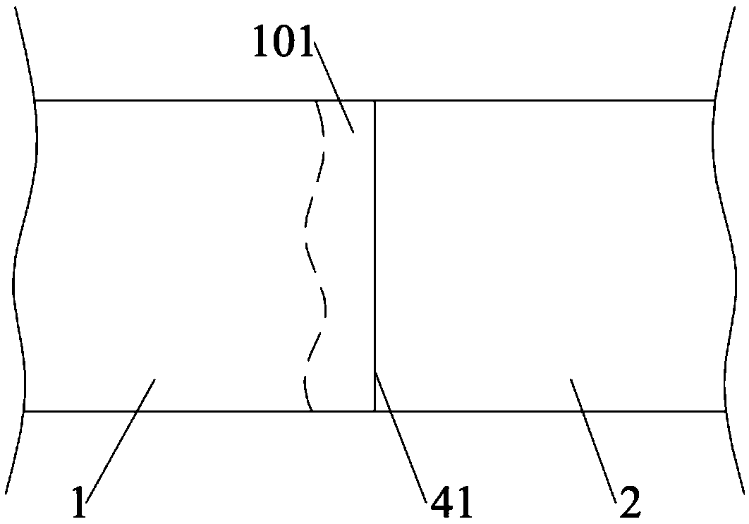
[0038] Such as Figures 1 to 2 As shown, this embodiment provides a multi-color spraying process for forming colors on a surface. The surface is the shell surface of an electronic device, may be the shell surface of a mobile phone, or may be the shell surface of a computer, and the material of the shell of the electronic device may be metal or plastic. A surface consists of at least two regions such as figure 1 As shown, the two adjacent areas are the first area 1 and the second area 2 respectively, there is a first dividing line 41 between the first area 1 and the second area 2, and the first area 1 is close to the second area 2 Part of the area is the first sub-area 101 .

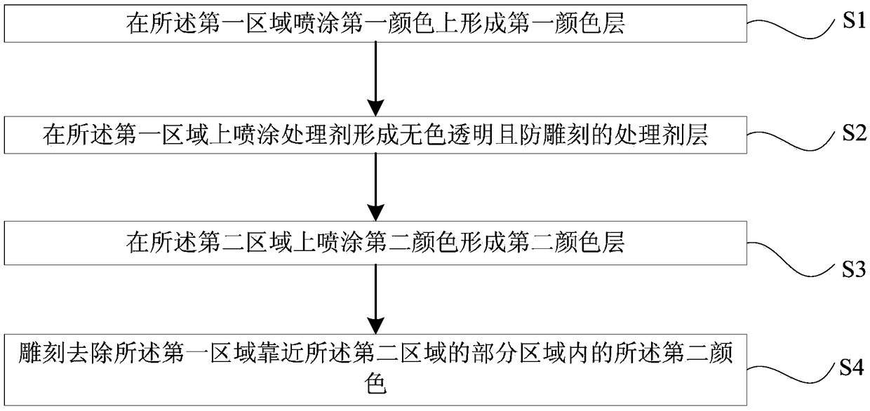
[0039] figure 2 It is the flow chart of multi-color spraying process in the present embodiment, with reference to figure 2 The multi-color spraying process is described in detail as follows:

[0040] S1: Spraying a first color on the first area 1 to form a first color layer.

[0041] S2: Spraying ...

Embodiment 2

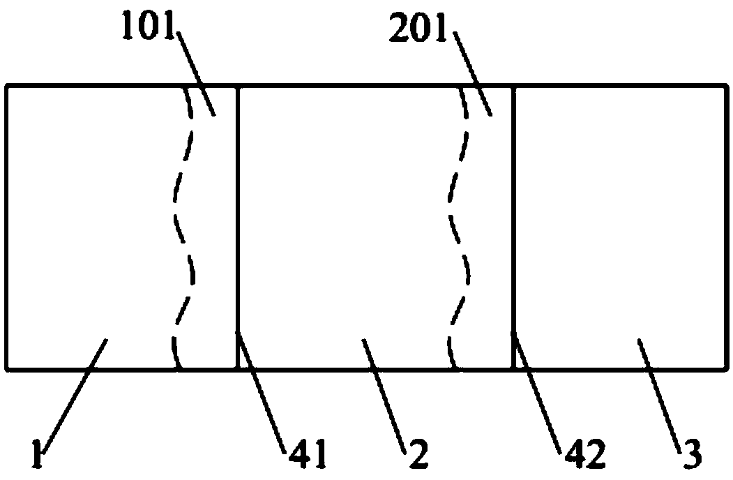
[0050] Such as image 3 As shown, when the surface includes three areas, respectively the first area 1, the second area 2 and the third area 3, the second area 2 is located between the first area 1 and the third area 3, the first area 1 and the third area There is a first boundary line 41 between the two regions 2, a second boundary line 42 between the second region 2 and the third region 3, and a part of the first region 1 close to the first boundary line 41 is the first sub-region 101, Part of the second area 2 close to the second boundary line 42 is the second sub-area 201 .

[0051] Figure 4 It is the flow chart of multi-color spraying process in the present embodiment, with reference to Figure 4 The multi-color spraying process is described in detail as follows:

[0052] S11: Spraying a first color on the first area 1 to form a first color layer.

[0053] S12: Spraying a treatment agent on the first area 1 to form a colorless, transparent and anti-engraving treatmen...

Embodiment 3

[0066] This embodiment provides a multi-color spraying process. The difference from Embodiment 2 is that the part of the third area 3 close to the second dividing line 42 is the third sub-area 301, such as Figure 5 shown.

[0067] Figure 6 It is the flow chart of color spraying process in the present embodiment, with reference to Figure 6 The color spraying process is described in detail as follows:

[0068] S101: Spraying a first color on the first area 1 to form a first color layer, and spraying a third color on the third area 3 to form a third color layer.

[0069] S102: Spraying a treatment agent on the first region 1 and the third region 3 to form a colorless, transparent and anti-engraving treatment agent layer.

[0070] S103: Spraying a second color on the second region 2 to form a second color layer.

[0071] When spraying the second color in the second area 2, the range of the second color actually sprayed generally also includes the first sub-area 101 where th...


PUM


Abstract

The invention discloses a multi-color spraying process and belongs to the technical field of surface manufacturing processes of materials. By spraying a treatment agent layer to a first color layer, asecond color layer is not in direct contact with the first color layer even if a second color is sprayed to a first region when the second color is sprayed, so that interpenetration or fusion of thefirst color layer and the second color layer is avoided, and the original color and luster and brightness of the first color layer and the second color layer are guaranteed. In addition, interpenetration or fusion of the second color layer and the treatment agent layer is further avoided. When the second color layer in the first region is removed by means of a 3D laser carving technology, the surface of the treatment agent layer is not affected, so that the boundary between the first color layer and the second color layer is orderly and clear after the second color layer in the first region iscarved. The boundary of two colors on a curved surface or a turned part on a shell can be orderly and clear, and the surface of the treatment agent layer is level and smooth, and the sense of beautyof the surface appearance is improved.

Description

technical field [0001] The invention relates to the technical field of material surface processing technology, in particular to a multi-color spraying technology. Background technique [0002] With the development trend of users' increasingly personalized requirements for electronic equipment, more and more electronic equipment casings adopt multi-color pattern designs. In order to realize the design of multi-color patterns, it is necessary to form multi-color patterns pattern. [0003] One of the commonly used techniques in the existing spraying process is to use different colors of paint layers to cover different areas of the shell surface, and then use lasers of different powers to paint other colors than the required colors according to the colors that need to be revealed in each area. Layers are sculpted away, exposing the paint layer of the corresponding color, to achieve the effect of precise dividing lines of color areas. However, due to the extremely thin thicknes...

Claims


Application Information

Patent Timeline
IPC IPC(8): B05D5/06B05D3/00
CPCB05D3/007B05D5/065
Inventor 吴静
Owner SHENZHEN HUIYE COMM TECH
Learn More