Welding fire bucket
A technology of torch and main shaft, applied in the field of welding torch, which can solve the problems of inconvenient application and potential safety hazards of high-altitude welding torch, and achieve the effect of light weight, easy to carry and install, and convenient to carry
- Summary
- Abstract
- Description
- Claims
- Application Information
AI Technical Summary
Problems solved by technology
Method used
Image
Examples
specific Embodiment 1
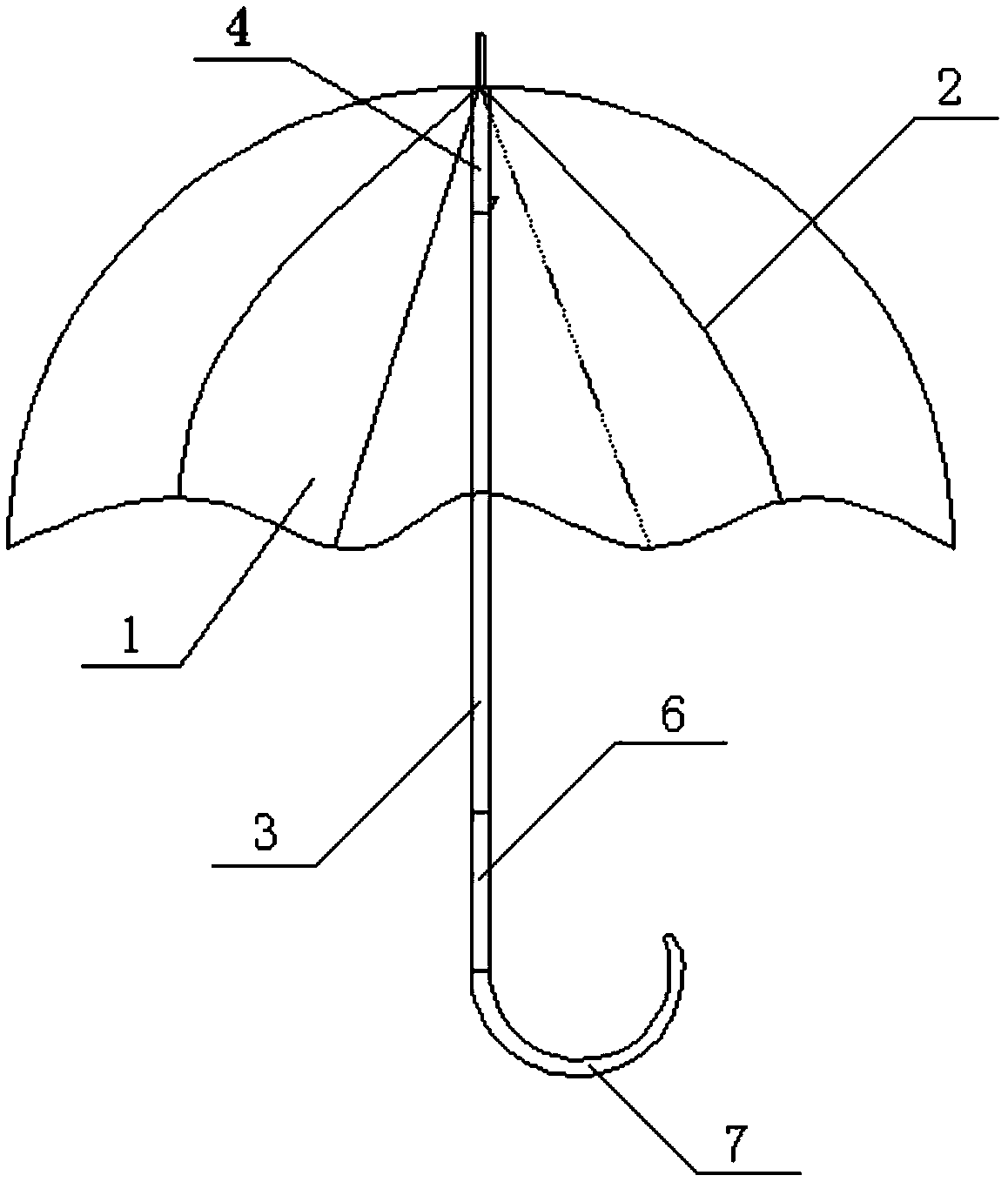
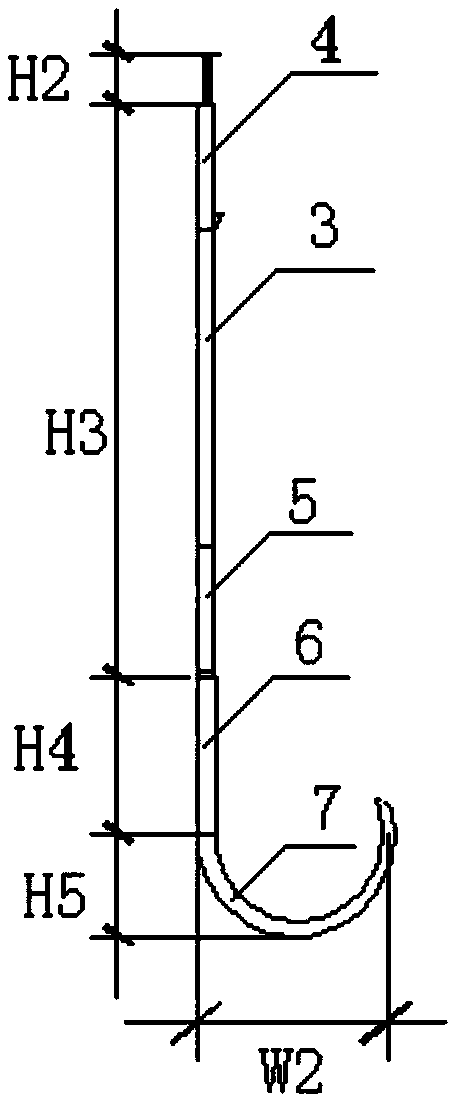
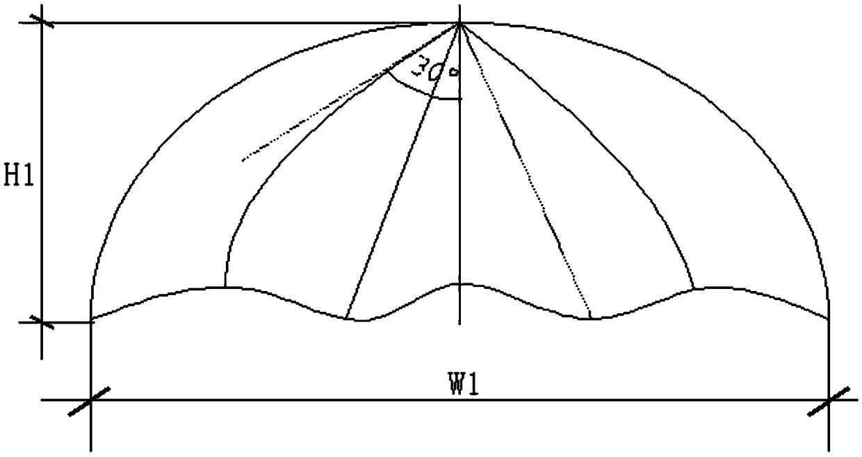
[0031] Specific embodiment one, such as figure 1 , figure 2 , image 3 Shown:
[0032] A welding fire bucket, comprising a fire bucket surface 1, a support assembly, and a telescopic drive assembly; wherein, the support assembly includes an umbrella-shaped support frame 2, a main shaft 3, and the telescopic drive assembly includes a fixed seat 4, a movable seat 5, and a fire bucket The surface 1 is fixed on the umbrella-shaped support frame 2, one end of the umbrella-shaped support frame 2 is connected with the fixed seat 4, and the other end is connected with the movable seat 5, the fixed seat 4 is fixedly installed on one end of the main shaft 3, and the movable seat 5 is movably socketed on the on the main shaft 3 and can move along the main shaft 3.
[0033] In this embodiment, the dimensions of each part are as shown in the figure, W1=1000mm, H1=700mm, W2=150mm, H2=50mm, H3=1000mm, H4=100mm, H5=50mm, and the dimensions of each part are only described as an example , ...
specific Embodiment 2
[0035] A welding fire bucket, comprising a fire bucket surface 1, a support assembly, and a telescopic drive assembly; wherein, the support assembly includes an umbrella-shaped support frame 2, a main shaft 3, and the telescopic drive assembly includes a fixed seat 4, a movable seat 5, and a fire bucket The surface 1 is fixed on the umbrella-shaped support frame 2, one end of the umbrella-shaped support frame 2 is connected with the fixed seat 4, and the other end is connected with the movable seat 5, the fixed seat 4 is fixedly installed on one end of the main shaft 3, and the movable seat 5 is movably socketed on the On the main shaft 3, a control component is arranged on the main shaft 3 to control the moving direction and the moving distance of the moving seat 5 on the main shaft 3. The control component described in this embodiment is a control button, and the movement of the moving seat along the main shaft is controlled by the button.
specific Embodiment 3
[0037] A welding fire bucket, comprising a fire bucket surface 1, a support assembly, and a telescopic drive assembly; wherein, the support assembly includes an umbrella-shaped support frame 2, a main shaft 3, and the telescopic drive assembly includes a fixed seat 4, a movable seat 5, and a fire bucket The surface 1 is fixed on the umbrella-shaped support frame 2, one end of the umbrella-shaped support frame 2 is connected with the fixed seat 4, and the other end is connected with the movable seat 5, the fixed seat 4 is fixedly installed on one end of the main shaft 3, and the movable seat 5 is movably socketed on the On the main shaft 3, a control button is set on the main shaft 3, and a stepping motor connected to the control button and the moving seat is arranged on the moving seat 5, the control button controls the stepping motor to work, and the stepping motor drives the moving seat to move along the main shaft, and the moving seat is moved through the control button. The...
PUM
 Abstract
Description
Claims
Application Information
 - R&D
- Intellectual Property
- Life Sciences
- Materials
- Tech Scout
- Unparalleled Data Quality
- Higher Quality Content
- 60% Fewer Hallucinations
Browse by: Latest US Patents, China's latest patents, Technical Efficacy Thesaurus, Application Domain, Technology Topic, Popular Technical Reports.
© 2025 PatSnap. All rights reserved.Legal|Privacy policy|Modern Slavery Act Transparency Statement|Sitemap|About US| Contact US: help@patsnap.com


