
A high-efficiency and low-emission biomass furnace

A biomass stove, low-emission technology, applied in the direction of household stoves/stoves, efficiency improvement of home appliances, lighting and heating equipment, etc., can solve the problems of inability to ensure safe use indoors, carbon monoxide poisoning, carbon monoxide reduction, etc., and achieve long burning time for heating , increase the utilization rate, the effect of simple structure

Active Publication Date: 2018-01-05
YONGKANG YAJUE IND & TRADE
View PDF7 Cites 0 Cited by
  • Summary
  • Abstract
  • Description
  • Claims
  • Application Information

AI Technical Summary

Problems solved by technology

Although the bottom-up combustion method of the traditional biomass furnace can facilitate the continuous addition of fuel, since the structure of the furnace body cannot be completely sealed, this combustion cycle method cannot prevent the exhaust gas from burning from overflowing from the gap in the furnace cavity. Incomplete combustion of toxic and harmful gases such as carbon monoxide will overflow and permeate the room, making the human body feel uncomfortable and even carbon monoxide poisoning
[0004] The improvement of the existing technology usually adopts the method of secondary gasification, such as the application number: CN201510242505.3, the name of the invention patent: the method and system for realizing carbon emission reduction by using a gasification furnace, and the application number: CN200710078420.1, the name of the invention patent : Household biomass gasifier and its production method, etc., all reduce carbon monoxide emissions by secondary gasification, but do not change the traditional bottom-up combustion method
Although the emission of carbon monoxide has been reduced to a certain extent, it still cannot fundamentally solve the problem that the combustion exhaust gas will overflow indoors, and the best effect of indoor safe use cannot be guaranteed.

Method used


Image

  • A high-efficiency and low-emission biomass furnace

Examples


Embodiment Construction

[0031] Below in conjunction with accompanying drawing, the present invention is described in detail.

[0032] In order to make the object, technical solution and advantages of the invention clearer, the present invention will be further described in detail below in conjunction with the accompanying drawings and embodiments. It should be understood that the specific embodiments described here are only used to explain the present invention, not to limit the present invention.

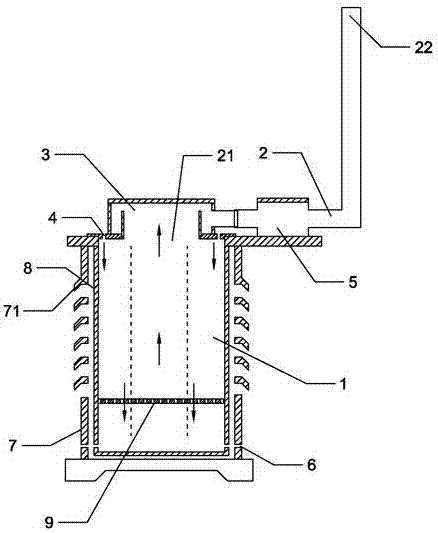
[0033] Such as figure 1As shown, a high-efficiency and low-emission biomass furnace includes a furnace body 1, an exhaust passage 2 connected to the furnace body 1, and an air intake passage. The air intake passage includes several main stove air inlets 4, and the main stove air inlet 4 is arranged on the top of the furnace body 1 and communicates with the inside of the furnace body 1 . The exhaust channel 2 includes an exhaust channel inlet 21 and an exhaust channel outlet 22 , and the exhaust channel ...


PUM


Abstract

The invention discloses an efficient low-emission biomass furnace, and belongs to the field of biomass furnaces. The efficient low-emission biomass furnace comprises a furnace body, an exhaust channel and an air inlet channel, and the exhaust channel and the air inlet channel are connected with the furnace body. The air inlet channel comprises a plurality of main stove air inlet holes, and the main stove air inlet holes are formed in the top of the furnace body and communicated with the furnace body. According to the biomass furnace, a traditional combustion method is subverted, a traditional biomass furnace concept constraint is abandoned, traditional convective circulation oxygen supply is converted into suck-back oxygen supply, and oxygen-enriched combustion is achieved. In the combustion process, air pressure in a main stove and a hearth is smaller than surrounding air pressure of the outside, a negative-pressure state is formed, and therefore combustion waste gas is prevented from overflowing. Under the condition that indoor aerobic combustion is guaranteed, the indoor waste gas emission is almost zero. The efficient low-emission biomass furnace is especially safe when used as an indoor cooking and heating furnace in the high and cold zones, and is incomparable with an existing traditional biomass furnace.

Description

technical field [0001] The invention relates to a biomass furnace, in particular to a high-efficiency and low-emission biomass furnace. Background technique [0002] The biomass furnace uses biomass materials, such as firewood, firewood, straw, corncobs, various husks, and various biomass briquettes, etc., and blows air through fans to fully gasify and burn the fuel in the furnace. So as to meet the functions of daily cooking, heating and boiling water. [0003] The traditional biomass furnace has a small furnace, the fuel is put into the furnace, the air is supplied from the bottom of the furnace, the combustion exhaust gas is discharged from the upper chimney, and the convective circulation oxygen supply from the bottom to the upper part of the furnace is completed through the suction of the chimney, and the fuel is from bottom to top combustion. Although the bottom-up combustion method of the traditional biomass furnace can facilitate the continuous addition of fuel, si...

Claims


Application Information

Patent Timeline
Patent Type & Authority Patents(China)
IPC IPC(8): F24B1/19F24B1/191
CPCF24B1/19F24B1/191Y02B40/00
Inventor 欧阳弟周德君
Owner YONGKANG YAJUE IND & TRADE
Learn More